How to Use SmartDriveDuo-10 (MBBS10): Examples, Pinouts, and Specs
Introduction
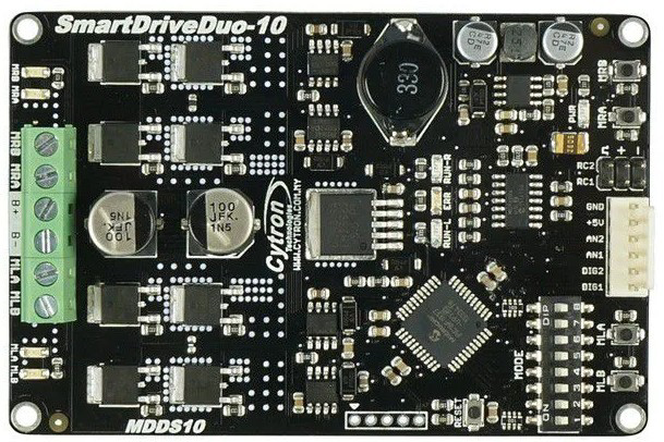
The SmartDriveDuo-10 (MBBS10) is a dual-channel motor driver manufactured by Cytron. It is designed to provide precise control of DC motors and stepper motors, making it an ideal choice for robotics and automation applications. With advanced control algorithms, integrated safety features, and a user-friendly interface, the SmartDriveDuo-10 ensures reliable and efficient motor operation. It supports various control modes, including PWM, RC (radio control), and analog input, offering flexibility for diverse projects.
Explore Projects Built with SmartDriveDuo-10 (MBBS10)

Explore Projects Built with SmartDriveDuo-10 (MBBS10)
Common Applications
- Robotics (e.g., mobile robots, robotic arms)
- Automated guided vehicles (AGVs)
- Conveyor systems
- CNC machines and 3D printers
- Educational and hobbyist projects
Technical Specifications
Key Technical Details
| Parameter | Specification |
|---|---|
| Operating Voltage | 7 V to 30 V |
| Continuous Current (per channel) | 10 A |
| Peak Current (per channel) | 30 A (for 10 seconds) |
| Control Modes | PWM, RC, Analog, UART |
| Motor Types Supported | DC motors, stepper motors |
| PWM Frequency | 16 kHz |
| Protection Features | Overcurrent, overtemperature, reverse polarity |
| Dimensions | 84 mm x 62 mm x 25 mm |
| Weight | 90 g |
Pin Configuration and Descriptions
The SmartDriveDuo-10 features multiple connectors for power, motor outputs, and control signals. Below is a detailed description of the pin configuration:
Power and Motor Output
| Pin/Connector Name | Description |
|---|---|
| VM | Motor power supply input (7 V to 30 V) |
| GND | Ground connection |
| M1A, M1B | Motor 1 output terminals |
| M2A, M2B | Motor 2 output terminals |
Control Input
| Pin/Connector Name | Description |
|---|---|
| PWM1, PWM2 | PWM input for Motor 1 and Motor 2 |
| DIR1, DIR2 | Direction control for Motor 1 and Motor 2 |
| AN1, AN2 | Analog input for Motor 1 and Motor 2 |
| RC1, RC2 | RC signal input for Motor 1 and Motor 2 |
| UART_TX, UART_RX | UART communication pins |
Status Indicators
| Indicator | Description |
|---|---|
| LED1, LED2 | Status LEDs for Motor 1 and Motor 2 |
| ERR_LED | Error indicator LED |
Usage Instructions
How to Use the SmartDriveDuo-10 in a Circuit
- Power Connection: Connect the VM pin to a DC power supply (7 V to 30 V) and the GND pin to the ground of the power supply.
- Motor Connection: Connect the motor terminals (M1A, M1B for Motor 1 and M2A, M2B for Motor 2) to the respective motor leads.
- Control Signal Input: Choose a control mode (PWM, RC, Analog, or UART) and connect the appropriate control pins to your microcontroller or signal source.
- Enable the Driver: Ensure the control signals are properly configured to enable motor operation.
Important Considerations and Best Practices
- Power Supply: Use a power supply capable of providing sufficient current for your motors. Ensure the voltage is within the specified range (7 V to 30 V).
- Heat Dissipation: The SmartDriveDuo-10 can handle high currents, but prolonged operation at peak current may cause overheating. Use a heatsink or active cooling if necessary.
- Control Mode Selection: Configure the control mode using the onboard DIP switches. Refer to the Cytron user manual for detailed instructions.
- Reverse Polarity Protection: The driver includes reverse polarity protection, but double-check your connections to avoid damage.
Example: Using SmartDriveDuo-10 with Arduino UNO
Below is an example of controlling two DC motors using PWM signals from an Arduino UNO:
// Example: Controlling two DC motors with SmartDriveDuo-10 and Arduino UNO

// Define PWM and direction pins for Motor 1 and Motor 2
const int PWM1 = 9;  // PWM pin for Motor 1
const int DIR1 = 8;  // Direction pin for Motor 1
const int PWM2 = 10; // PWM pin for Motor 2
const int DIR2 = 7;  // Direction pin for Motor 2

void setup() {
  // Set direction pins as outputs
  pinMode(DIR1, OUTPUT);
  pinMode(DIR2, OUTPUT);

  // Set initial motor directions
  digitalWrite(DIR1, HIGH); // Motor 1 forward
  digitalWrite(DIR2, LOW);  // Motor 2 reverse
}

void loop() {
  // Set motor speeds using PWM (0-255)
  analogWrite(PWM1, 128); // Motor 1 at 50% speed
  analogWrite(PWM2, 200); // Motor 2 at ~78% speed

  delay(2000); // Run motors for 2 seconds

  // Stop motors
  analogWrite(PWM1, 0);
  analogWrite(PWM2, 0);

  delay(1000); // Wait for 1 second before restarting
}
Troubleshooting and FAQs
Common Issues and Solutions
Motors Not Running
- Cause: Incorrect power supply connection or insufficient voltage.
- Solution: Verify the power supply voltage and ensure proper connections to the VM and GND pins.
Overheating
- Cause: Prolonged operation at high current or insufficient cooling.
- Solution: Add a heatsink or active cooling to the driver.
Erratic Motor Behavior
- Cause: Noise in control signals or incorrect control mode configuration.
- Solution: Use shielded cables for control signals and verify the DIP switch settings.
Error LED Lit
- Cause: Overcurrent, overtemperature, or other fault conditions.
- Solution: Check the motor load and ensure it is within the specified limits. Allow the driver to cool down if necessary.
FAQs
Q: Can the SmartDriveDuo-10 control stepper motors?
A: Yes, it can control stepper motors in certain configurations. Refer to the Cytron user manual for detailed instructions.
Q: What is the maximum PWM frequency supported?
A: The SmartDriveDuo-10 supports a PWM frequency of up to 16 kHz.
Q: Is it possible to use UART for motor control?
A: Yes, the SmartDriveDuo-10 supports UART communication for motor control. Ensure proper configuration of the UART_TX and UART_RX pins.
Q: Can I use the driver with a 24 V power supply?
A: Yes, the driver supports power supply voltages from 7 V to 30 V, including 24 V.