How to Use Makerverse 2 Channel Motor Driver: Examples, Pinouts, and Specs
Introduction
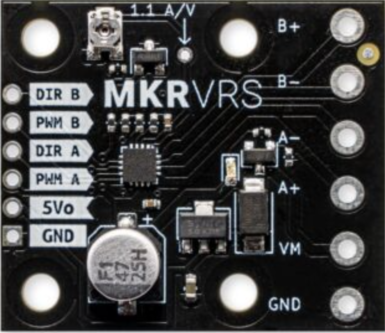
The Makerverse 2 Channel Motor Driver (Part ID: CE08038) is a versatile motor driver designed to control two DC motors simultaneously. It provides the necessary current and voltage to drive motors in both forward and reverse directions, making it ideal for robotics, automation, and other motor control applications. This motor driver is compatible with microcontrollers like Arduino, Raspberry Pi, and other development boards, enabling precise motor control for a wide range of projects.
Explore Projects Built with Makerverse 2 Channel Motor Driver


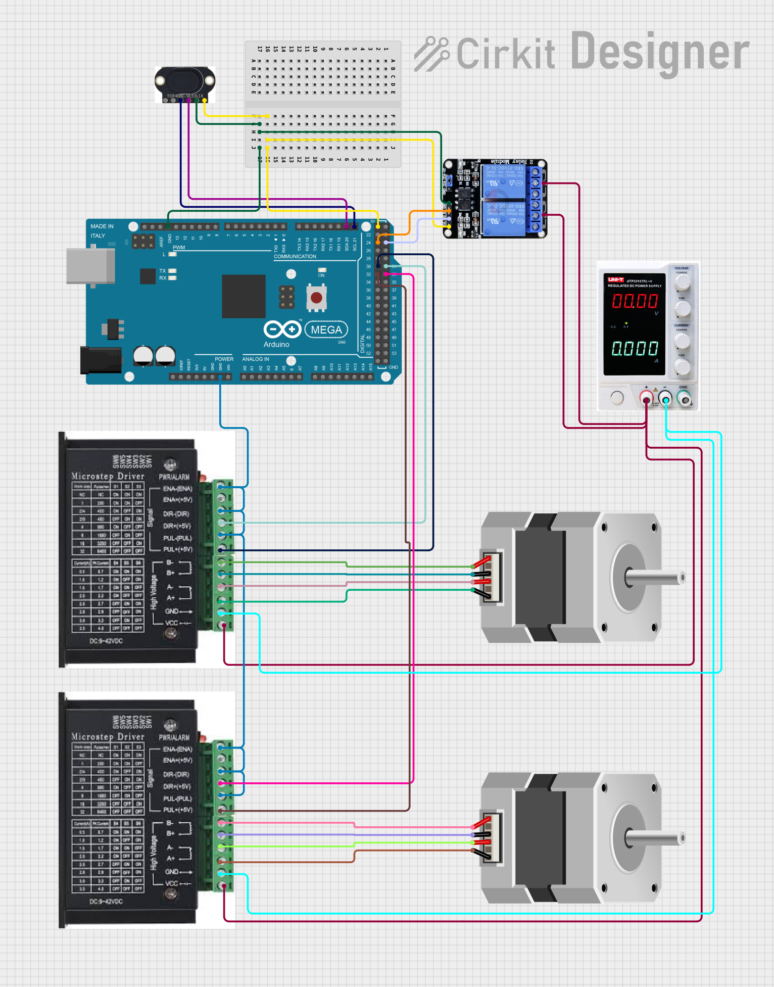
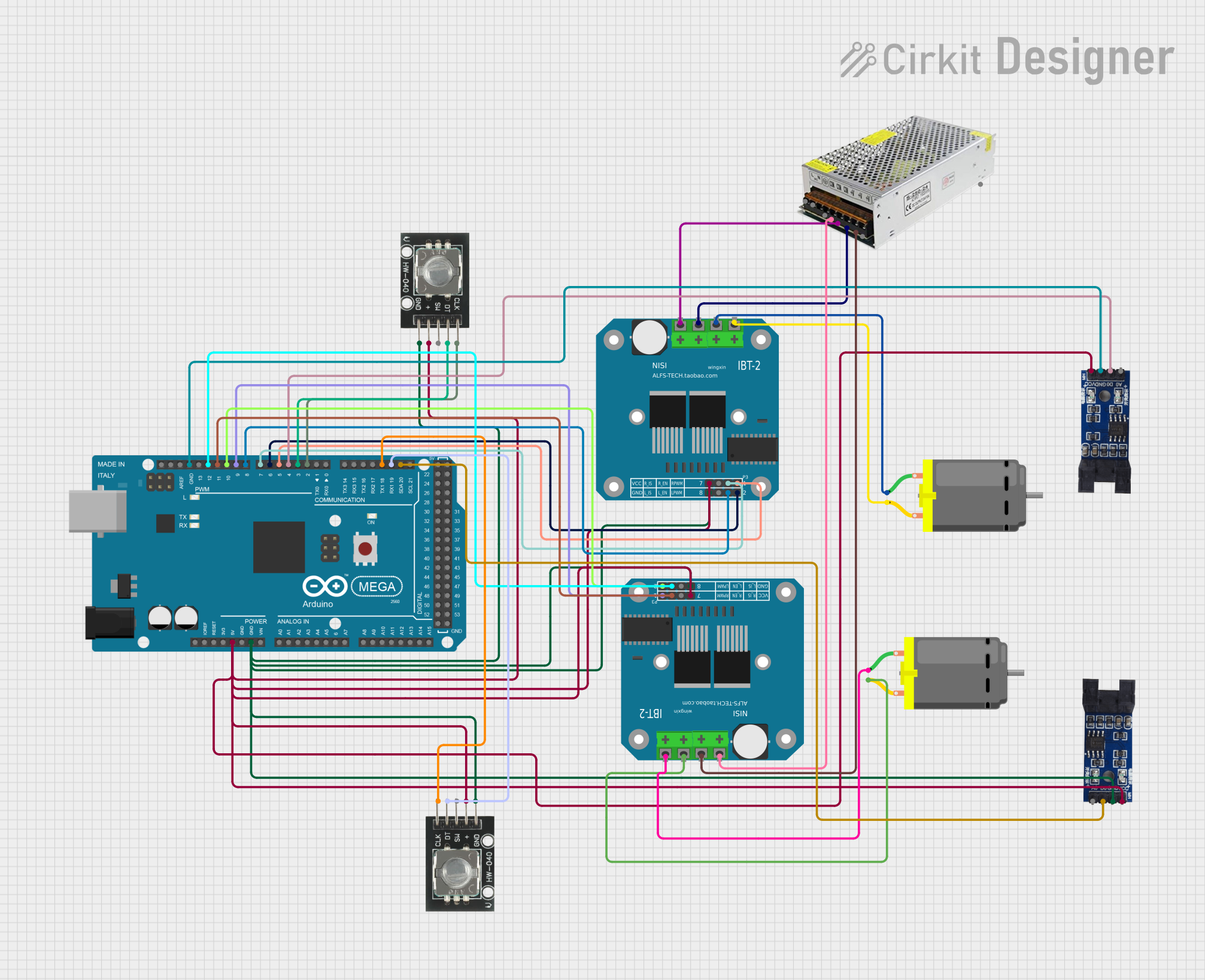
Explore Projects Built with Makerverse 2 Channel Motor Driver
Common Applications
- Robotics (e.g., controlling robot wheels or arms)
- Automated conveyor systems
- Remote-controlled vehicles
- DIY motorized projects
- Educational electronics projects
Technical Specifications
The following table outlines the key technical details of the Makerverse 2 Channel Motor Driver:
| Specification | Details |
|---|---|
| Manufacturer | Makerverse |
| Part ID | CE08038 |
| Operating Voltage | 6V to 12V |
| Maximum Motor Current | 1.5A per channel (continuous) |
| Peak Motor Current | 2A per channel (short duration) |
| Control Logic Voltage | 3.3V or 5V (logic level compatible) |
| Number of Channels | 2 |
| Motor Control Modes | Forward, Reverse, Brake, Stop |
| PWM Frequency | Up to 20 kHz |
| Dimensions | 50mm x 40mm x 15mm |
| Weight | 20g |
Pin Configuration and Descriptions
The Makerverse 2 Channel Motor Driver has the following pin layout:
| Pin Name | Type | Description |
|---|---|---|
| VIN | Power Input | Connect to the motor power supply (6V to 12V). |
| GND | Ground | Common ground for the motor driver and control circuit. |
| IN1 | Control Input | Logic input to control the direction of Motor 1. |
| IN2 | Control Input | Logic input to control the direction of Motor 1. |
| IN3 | Control Input | Logic input to control the direction of Motor 2. |
| IN4 | Control Input | Logic input to control the direction of Motor 2. |
| ENA | PWM Input | Enable pin for Motor 1. Accepts PWM signals for speed control. |
| ENB | PWM Input | Enable pin for Motor 2. Accepts PWM signals for speed control. |
| OUT1 | Motor Output | Connect to one terminal of Motor 1. |
| OUT2 | Motor Output | Connect to the other terminal of Motor 1. |
| OUT3 | Motor Output | Connect to one terminal of Motor 2. |
| OUT4 | Motor Output | Connect to the other terminal of Motor 2. |
Usage Instructions
Connecting the Motor Driver
- Power Supply: Connect the VIN pin to a power source (6V to 12V) and the GND pin to the ground of the power supply.
- Motor Connections:
- Connect Motor 1 terminals to OUT1 and OUT2.
- Connect Motor 2 terminals to OUT3 and OUT4.
- Control Pins:
- Connect IN1 and IN2 to the microcontroller pins for controlling Motor 1.
- Connect IN3 and IN4 to the microcontroller pins for controlling Motor 2.
- PWM Pins:
- Connect ENA to a PWM-capable pin on the microcontroller for Motor 1 speed control.
- Connect ENB to a PWM-capable pin on the microcontroller for Motor 2 speed control.
Arduino Example Code
Below is an example of how to control two DC motors using an Arduino UNO:
// Define motor control pins
#define IN1 7  // Motor 1 direction control pin
#define IN2 8  // Motor 1 direction control pin
#define ENA 9  // Motor 1 speed control (PWM) pin
#define IN3 10 // Motor 2 direction control pin
#define IN4 11 // Motor 2 direction control pin
#define ENB 6  // Motor 2 speed control (PWM) pin

void setup() {
  // Set motor control pins as outputs
  pinMode(IN1, OUTPUT);
  pinMode(IN2, OUTPUT);
  pinMode(ENA, OUTPUT);
  pinMode(IN3, OUTPUT);
  pinMode(IN4, OUTPUT);
  pinMode(ENB, OUTPUT);
}

void loop() {
  // Motor 1: Forward at 50% speed
  digitalWrite(IN1, HIGH); // Set IN1 high
  digitalWrite(IN2, LOW);  // Set IN2 low
  analogWrite(ENA, 128);   // Set ENA to 50% duty cycle (128/255)

  // Motor 2: Reverse at 75% speed
  digitalWrite(IN3, LOW);  // Set IN3 low
  digitalWrite(IN4, HIGH); // Set IN4 high
  analogWrite(ENB, 192);   // Set ENB to 75% duty cycle (192/255)

  delay(2000); // Run motors for 2 seconds

  // Stop both motors
  digitalWrite(IN1, LOW);
  digitalWrite(IN2, LOW);
  digitalWrite(IN3, LOW);
  digitalWrite(IN4, LOW);
  analogWrite(ENA, 0);
  analogWrite(ENB, 0);

  delay(2000); // Wait for 2 seconds before repeating
}
Important Considerations
- Ensure the motor power supply voltage matches the motor's operating voltage.
- Do not exceed the maximum current rating (1.5A continuous, 2A peak) to avoid damaging the driver.
- Use appropriate heat dissipation methods if operating near the maximum current for extended periods.
- Always connect the GND pin of the motor driver to the ground of the microcontroller to ensure proper operation.
Troubleshooting and FAQs
Common Issues
Motors not spinning:
- Verify that the power supply is connected and providing the correct voltage.
- Check the control pins (IN1, IN2, IN3, IN4) for proper logic signals.
- Ensure the GND pin is connected to the microcontroller's ground.
Motors spinning in the wrong direction:
- Reverse the connections of the motor terminals (OUT1/OUT2 or OUT3/OUT4).
- Swap the logic levels of the corresponding control pins (e.g., IN1 and IN2).
Motor speed not adjustable:
- Ensure the ENA and ENB pins are connected to PWM-capable pins on the microcontroller.
- Verify that the PWM signal is being generated correctly.
Overheating:
- Check if the motor current exceeds the driver's maximum rating.
- Use a heat sink or cooling fan if necessary.
FAQs
Q: Can I use this motor driver with a 3.3V microcontroller?
A: Yes, the Makerverse 2 Channel Motor Driver is compatible with both 3.3V and 5V logic levels.
Q: What type of motors can I control with this driver?
A: This driver is designed for brushed DC motors with operating voltages between 6V and 12V.
Q: Can I control only one motor with this driver?
A: Yes, you can use only one channel if needed. Leave the unused channel's pins unconnected.
Q: Is this driver suitable for stepper motors?
A: No, this driver is specifically designed for DC motors. Use a dedicated stepper motor driver for stepper motors.