
How to Use 74HC4067: Examples, Pinouts, and Specs
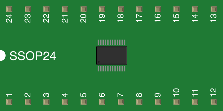
 Design with 74HC4067 in Cirkit Designer
Introduction
The 74HC4067 is a high-speed CMOS 16-channel analog multiplexer/demultiplexer manufactured by Nexperia. It allows one of 16 input/output channels to be connected to a single common terminal, controlled by a 4-bit binary address. This versatile component is widely used in applications requiring signal routing, such as data acquisition systems, sensor arrays, and audio signal switching.
Explore Projects Built with 74HC4067
 Open Project in Cirkit Designer
 Open Project in Cirkit Designer
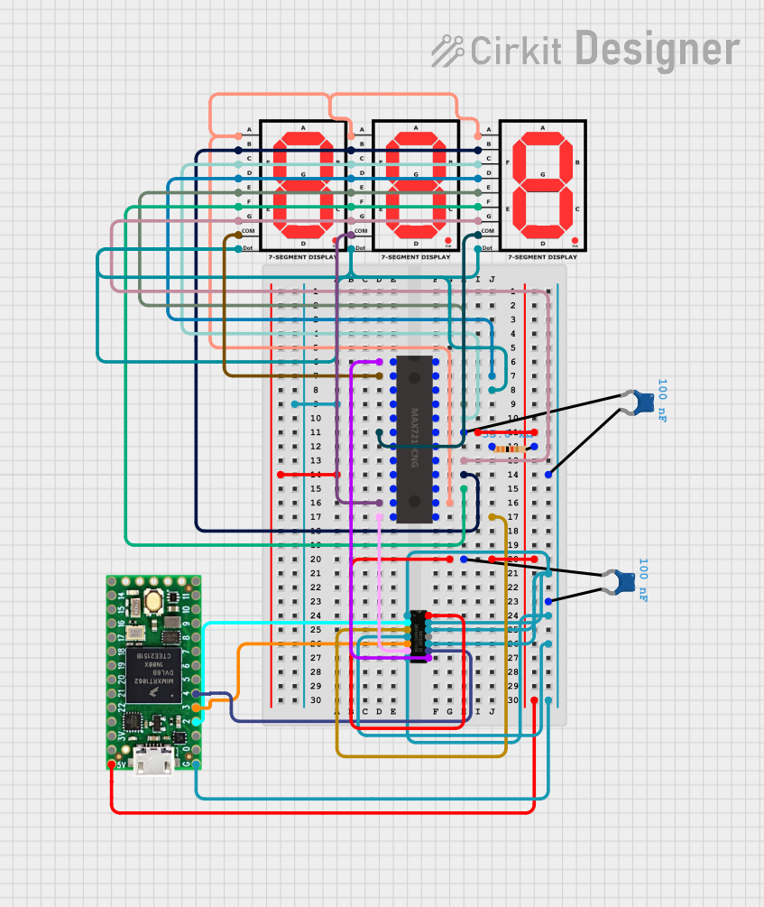 Open Project in Cirkit Designer
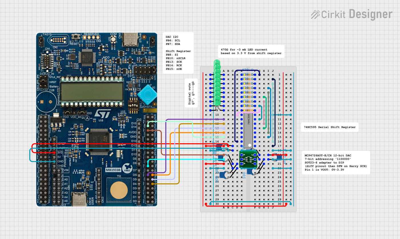 Open Project in Cirkit Designer
Explore Projects Built with 74HC4067
Open Project in Cirkit DesignerOpen Project in Cirkit DesignerOpen Project in Cirkit DesignerOpen Project in Cirkit DesignerCommon Applications
- Signal multiplexing in microcontroller-based systems
- Sensor data acquisition
- Audio signal routing
- Expanding the number of analog inputs for microcontrollers
- Digital-to-analog and analog-to-digital conversion systems
Technical Specifications
The following table outlines the key technical details of the 74HC4067:
| Parameter | Value |
|---|---|
| Supply Voltage (Vcc) | 2V to 6V |
| Input Voltage Range | 0V to Vcc |
| Maximum Current per Pin | ±25mA |
| Power Dissipation | 500mW |
| Propagation Delay | ~10ns (at Vcc = 5V) |
| Operating Temperature | -40°C to +125°C |
| Package Types | SOIC, TSSOP, DIP |
Pin Configuration and Descriptions
The 74HC4067 has 24 pins, with the following configuration:
| Pin Number | Pin Name | Description |
|---|---|---|
| 1-8 | Y0-Y7 | Channel inputs/outputs 0 to 7 |
| 9 | E (EN) | Enable pin (active LOW) |
| 10-13 | S0-S3 | Address selection pins (binary control) |
| 14 | VEE | Negative supply voltage (connect to GND for single-supply operation) |
| 15-22 | Y8-Y15 | Channel inputs/outputs 8 to 15 |
| 23 | Z | Common input/output terminal |
| 24 | VCC | Positive supply voltage |
Usage Instructions
The 74HC4067 is straightforward to use in both analog and digital circuits. Below are the steps and considerations for proper usage:
Connecting the Component
- Power Supply: Connect the VCC pin to a voltage source (2V to 6V) and the VEE pin to ground (0V) for single-supply operation.
- Enable Pin: The E (EN) pin must be set LOW to enable the multiplexer. If set HIGH, all channels are disconnected.
- Channel Selection: Use the S0-S3 pins to select one of the 16 channels. The binary value on these pins determines the active channel:
- Example:
S3 S2 S1 S0 = 0000selects channel Y0, and1111selects channel Y15.
- Example:
- Signal Connections: Connect the signals to the Y0-Y15 pins. The selected channel will be routed to the Z pin.
Example Circuit with Arduino UNO
The 74HC4067 can be used with an Arduino UNO to expand the number of analog inputs. Below is an example of how to connect and control the multiplexer:
Circuit Connections
- Connect VCC to the Arduino's 5V pin and VEE to GND.
- Connect the E (EN) pin to GND to enable the multiplexer.
- Connect the S0-S3 pins to Arduino digital pins (e.g., D2-D5).
- Connect the Z pin to an Arduino analog input (e.g., A0).
- Connect sensors or signals to the Y0-Y15 pins.
Arduino Code Example
// Define control pins for the 74HC4067
const int S0 = 2;  // Address pin S0
const int S1 = 3;  // Address pin S1
const int S2 = 4;  // Address pin S2
const int S3 = 5;  // Address pin S3
const int Z = A0;  // Common terminal connected to Arduino analog pin

void setup() {
  // Set address pins as outputs
  pinMode(S0, OUTPUT);
  pinMode(S1, OUTPUT);
  pinMode(S2, OUTPUT);
  pinMode(S3, OUTPUT);

  // Initialize serial communication for debugging
  Serial.begin(9600);
}

void loop() {
  for (int channel = 0; channel < 16; channel++) {
    // Set the address pins to select the channel
    digitalWrite(S0, channel & 0x01);  // Least significant bit
    digitalWrite(S1, (channel >> 1) & 0x01);
    digitalWrite(S2, (channel >> 2) & 0x01);
    digitalWrite(S3, (channel >> 3) & 0x01);

    // Read the analog value from the selected channel
    int value = analogRead(Z);

    // Print the channel number and value to the serial monitor
    Serial.print("Channel ");
    Serial.print(channel);
    Serial.print(": ");
    Serial.println(value);

    delay(500);  // Wait for 500ms before switching to the next channel
  }
}
Best Practices
- Use decoupling capacitors (e.g., 0.1µF) near the VCC pin to reduce noise.
- Avoid exceeding the voltage and current ratings to prevent damage.
- For high-frequency signals, consider the propagation delay and crosstalk between channels.
Troubleshooting and FAQs
Common Issues
No Signal on Output (Z) Pin:
- Ensure the E (EN) pin is LOW to enable the multiplexer.
- Verify the binary address on the S0-S3 pins matches the desired channel.
Incorrect Channel Selection:
- Check the wiring of the S0-S3 pins to the microcontroller.
- Ensure the binary address is correctly set in the code or circuit.
Signal Distortion:
- Verify the input signal voltage is within the range of 0V to VCC.
- Use proper grounding and shielding to minimize noise.
FAQs
Q: Can the 74HC4067 handle digital signals?
A: Yes, the 74HC4067 can route both analog and digital signals, provided the voltage levels are within the specified range.
Q: What happens if the enable pin is HIGH?
A: When the E (EN) pin is HIGH, all channels are disconnected, and the Z pin is in a high-impedance state.
Q: Can I use the 74HC4067 with a 3.3V microcontroller?
A: Yes, the 74HC4067 operates with supply voltages as low as 2V, making it compatible with 3.3V systems.
Q: Is it possible to cascade multiple 74HC4067 chips?
A: Yes, you can cascade multiple chips to expand the number of channels. Use additional address lines or enable pins to control each chip independently.