
How to Use Adafruit Micro USB Breakout: Examples, Pinouts, and Specs
 Design with Adafruit Micro USB Breakout in Cirkit Designer
Introduction
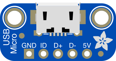
The Adafruit Micro USB Breakout (Manufacturer Part ID: 1833) is a compact and versatile printed circuit board (PCB) designed to simplify the integration of micro USB connectivity into your electronic projects. It provides an easy way to connect a micro USB cable for power delivery and data transfer, making it ideal for prototyping and custom designs.
This breakout board is particularly useful for projects requiring USB communication or power input, such as microcontroller-based systems, battery charging circuits, or USB-powered devices. Its small size and straightforward design make it a popular choice for hobbyists and professionals alike.
Explore Projects Built with Adafruit Micro USB Breakout
 Open Project in Cirkit Designer
 Open Project in Cirkit Designer
 Open Project in Cirkit Designer
 Open Project in Cirkit Designer
Explore Projects Built with Adafruit Micro USB Breakout
Open Project in Cirkit DesignerOpen Project in Cirkit DesignerOpen Project in Cirkit DesignerOpen Project in Cirkit DesignerCommon Applications
- Powering small electronic devices via USB
- USB data communication with microcontrollers (e.g., Arduino, Raspberry Pi)
- Prototyping USB-powered circuits
- Battery charging circuits with USB input
- Custom USB-enabled hardware designs
Technical Specifications
The Adafruit Micro USB Breakout is designed to provide reliable and easy access to the micro USB interface. Below are its key technical details:
Key Specifications
- Connector Type: Micro USB Type B (female)
- Voltage Rating: 5V (standard USB voltage)
- Current Rating: Up to 1.8A (depending on the USB source)
- PCB Dimensions: 15mm x 12mm (0.6" x 0.47")
- Mounting Holes: Two 2mm holes for secure attachment
- Pin Pitch: 2.54mm (0.1") for breadboard compatibility
Pin Configuration and Descriptions
The breakout board exposes the following pins for easy connection:
| Pin Name | Description |
|---|---|
| VBUS | 5V power from the USB cable. Can be used to power your circuit. |
| GND | Ground connection. Common ground for power and data. |
| D+ | USB data positive line. Used for data communication. |
| D- | USB data negative line. Used for data communication. |
| ID | Identification pin. Typically unused in most projects. |
Usage Instructions
The Adafruit Micro USB Breakout is simple to use and can be integrated into a variety of projects. Follow the steps below to use it effectively:
Connecting the Breakout Board
- Power Supply: Connect the
VBUSpin to the power input of your circuit and theGNDpin to the ground. This will supply 5V power from the USB cable to your project. - Data Communication: If your project requires USB data transfer, connect the
D+andD-pins to the corresponding data lines of your microcontroller or USB-enabled device. - Mounting: Use the two mounting holes to securely attach the breakout board to your project enclosure or PCB.
Important Considerations
- Voltage Regulation: Ensure that your circuit can handle the 5V provided by the USB cable. If your components require lower voltages, use a voltage regulator.
- Current Limitations: The maximum current available depends on the USB source. Standard USB ports typically provide up to 500mA, while USB 3.0 ports or dedicated chargers can supply higher currents.
- Data Lines: If you are not using the data lines (
D+andD-), leave them unconnected to avoid interference.
Example: Connecting to an Arduino UNO
The Adafruit Micro USB Breakout can be used to power an Arduino UNO or enable USB communication. Below is an example of how to connect it:
- Connect the
VBUSpin to the Arduino's5Vpin. - Connect the
GNDpin to the Arduino'sGNDpin. - If USB data communication is required, connect the
D+andD-pins to the appropriate USB data pins on the Arduino.
Arduino Code Example
If you are using the breakout board for USB communication, you can use the following Arduino sketch to send data over USB:
// Example Arduino sketch for USB communication
// This sketch sends "Hello, USB!" over the serial connection.

void setup() {
  Serial.begin(9600); // Initialize serial communication at 9600 baud
  while (!Serial) {
    // Wait for the serial connection to be established
    delay(10);
  }
  Serial.println("Hello, USB!"); // Send a message over USB
}

void loop() {
  // Continuously send a message every second
  Serial.println("This is a test message from Arduino.");
  delay(1000); // Wait for 1 second
}
Troubleshooting and FAQs
Common Issues
No Power to the Circuit
- Cause: The USB cable may not be properly connected, or the
VBUSandGNDpins are not correctly wired. - Solution: Check the USB cable connection and ensure the
VBUSandGNDpins are securely connected to your circuit.
- Cause: The USB cable may not be properly connected, or the
Data Communication Not Working
- Cause: The
D+andD-pins may not be connected correctly, or the microcontroller is not configured for USB communication. - Solution: Verify the connections of the
D+andD-pins. Ensure your microcontroller's USB communication settings are correctly configured.
- Cause: The
Overheating
- Cause: Excessive current draw from the USB source.
- Solution: Ensure your circuit does not exceed the current rating of the USB source. Use a powered USB hub if necessary.
FAQs
Q: Can I use this breakout board to charge a battery?
A: Yes, you can use the breakout board to provide 5V power for a battery charging circuit. However, ensure that your charging circuit is designed to handle USB input.
Q: Is the breakout board compatible with USB 3.0?
A: Yes, the breakout board is compatible with USB 3.0, but it only supports USB 2.0 data rates.
Q: Can I use this breakout board with a Raspberry Pi?
A: Yes, the breakout board can be used to power a Raspberry Pi or enable USB communication with it.
By following this documentation, you can effectively integrate the Adafruit Micro USB Breakout into your projects for reliable power and data transfer.