How to Use SERVO MOTOR: Examples, Pinouts, and Specs

Introduction
The UNO MG995 Servo Motor is a high-torque, high-speed rotary actuator designed for precise control of angular position, velocity, and acceleration. It integrates a motor with a position feedback sensor, making it ideal for applications requiring accurate and repeatable movements. Common applications include robotics, RC vehicles, and automated machinery.
Explore Projects Built with SERVO MOTOR
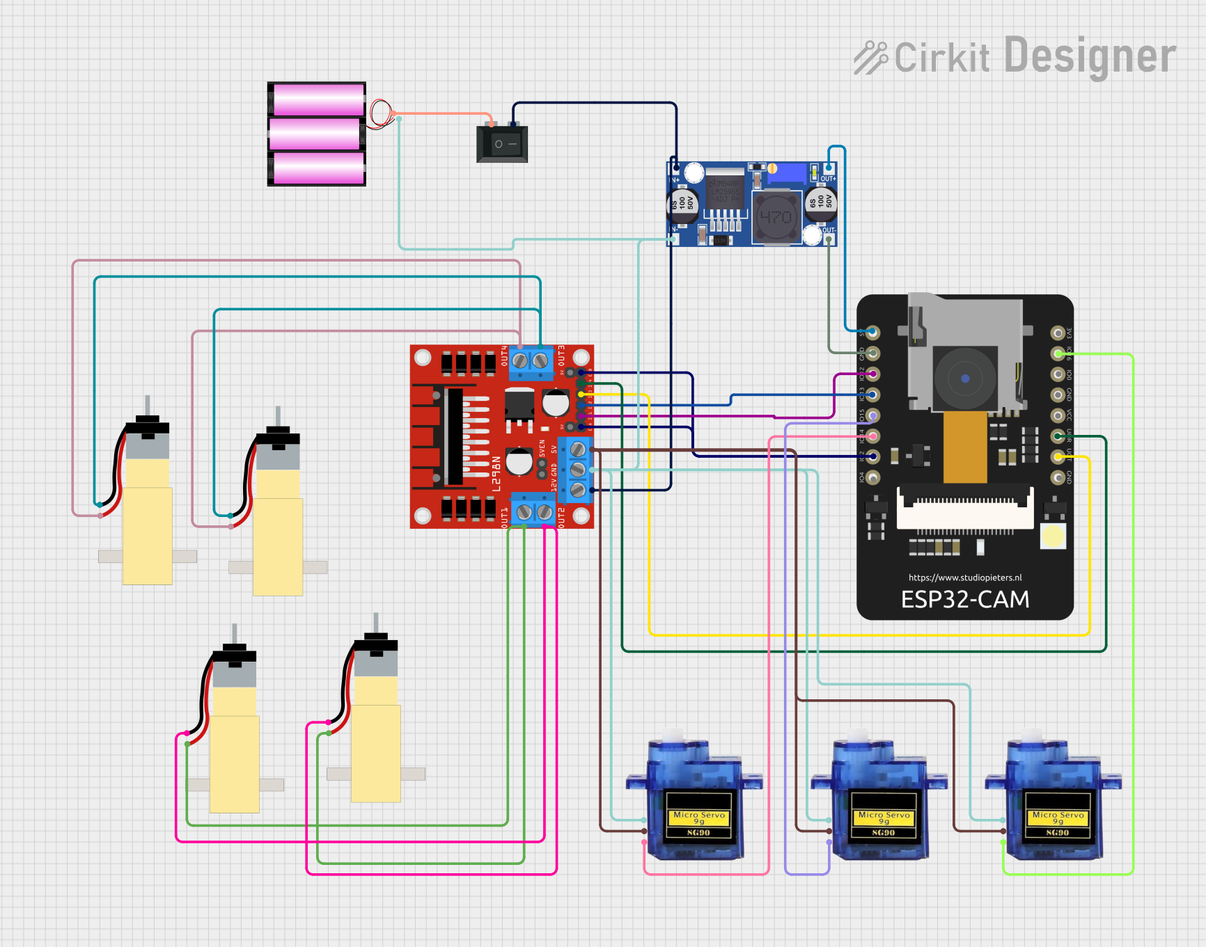
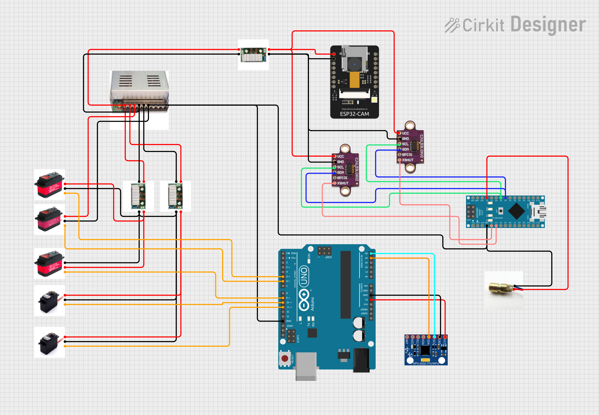
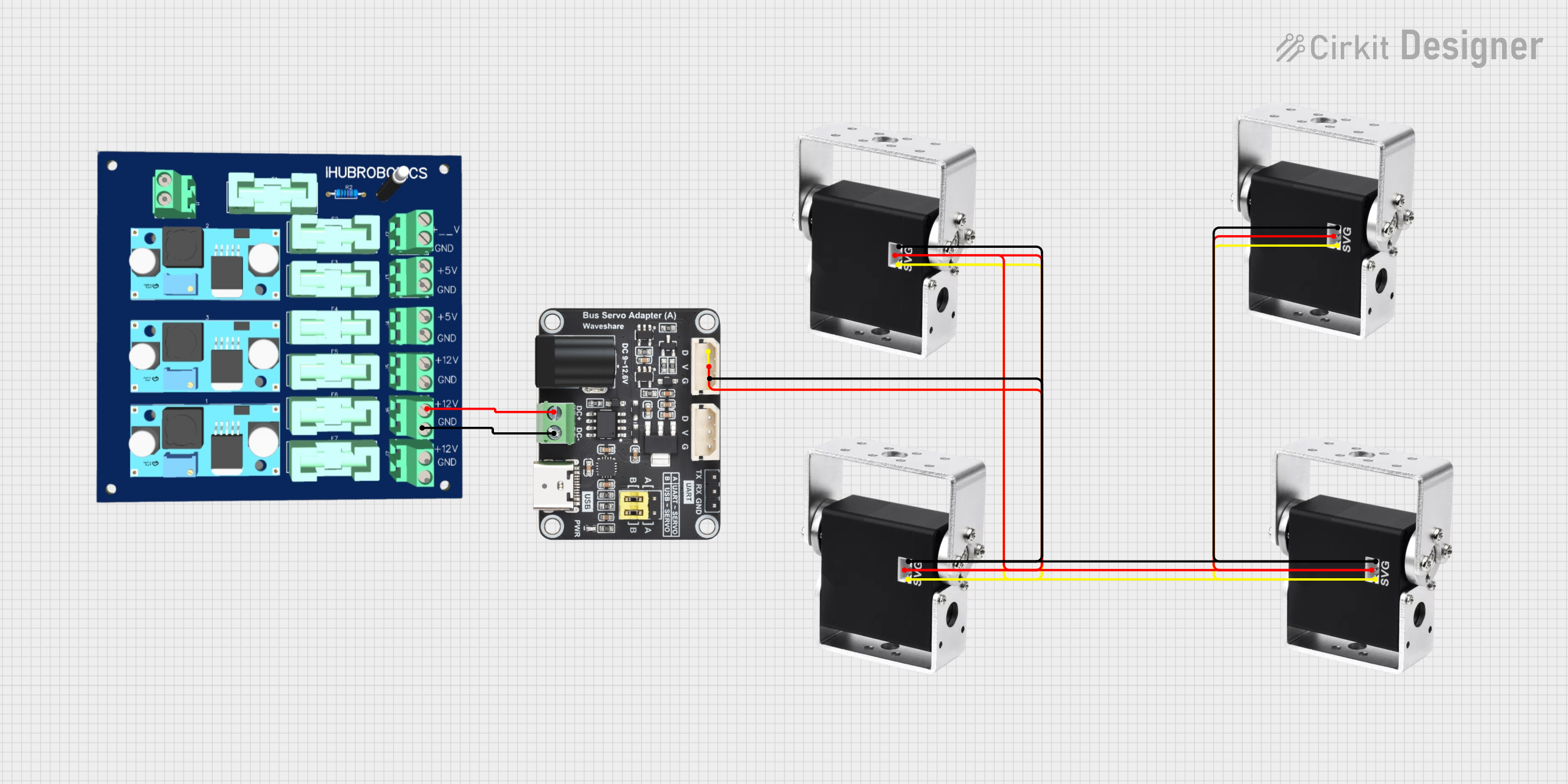
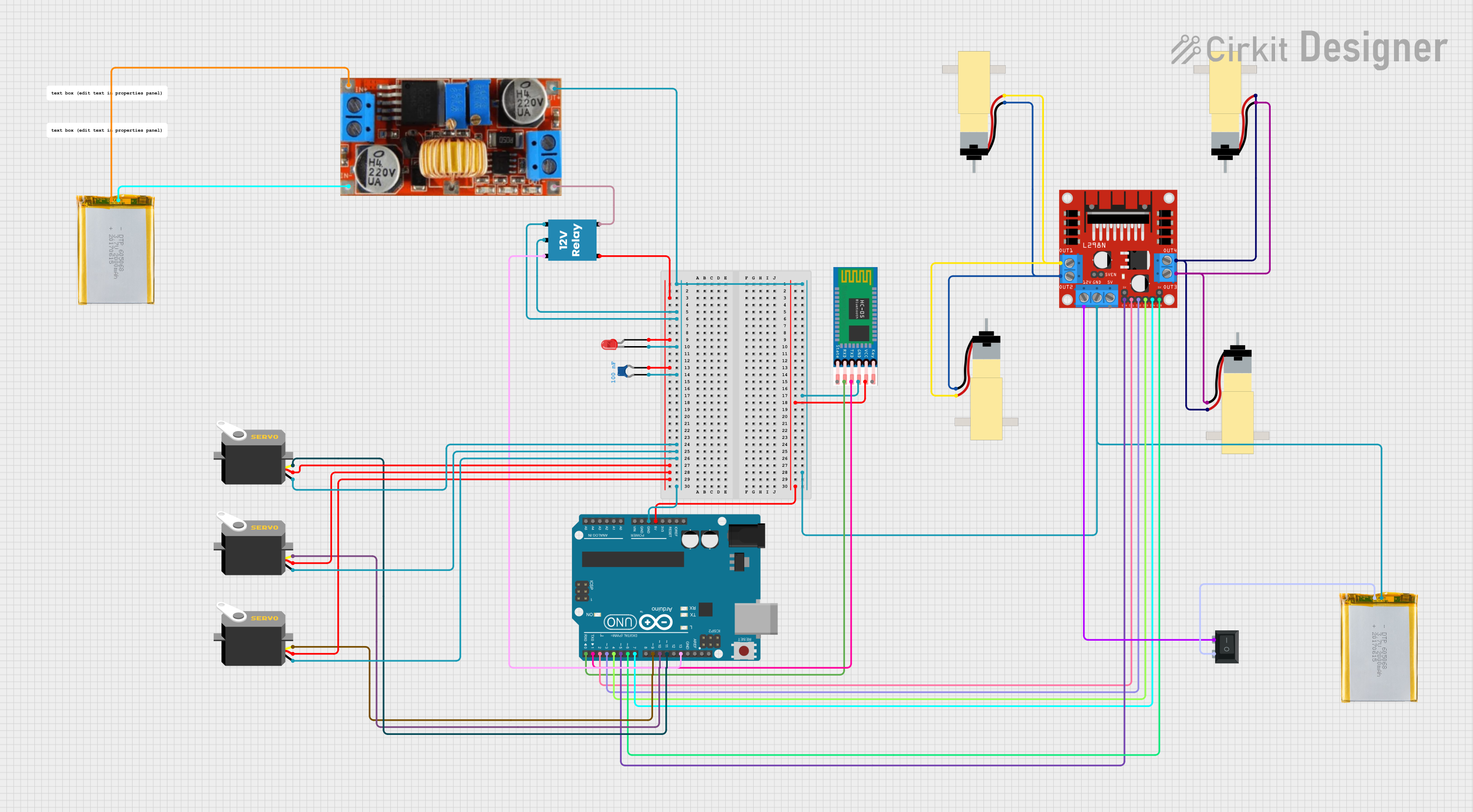
Explore Projects Built with SERVO MOTOR
Technical Specifications
Key Technical Details
| Parameter | Value |
|---|---|
| Operating Voltage | 4.8V - 7.2V |
| Stall Torque | 9.4 kg-cm (4.8V), 11 kg-cm (6V) |
| Operating Speed | 0.20 sec/60° (4.8V), 0.16 sec/60° (6V) |
| Current Draw (Idle) | 10 mA |
| Current Draw (No Load) | 170 mA |
| Current Draw (Stall) | 1.2 A |
| Dimensions | 40.7 x 19.7 x 42.9 mm |
| Weight | 55 g |
Pin Configuration and Descriptions
| Pin Number | Pin Name | Description |
|---|---|---|
| 1 | GND | Ground |
| 2 | VCC | Power Supply (4.8V - 7.2V) |
| 3 | Signal | PWM Signal Input for Position Control |
Usage Instructions
How to Use the Component in a Circuit
- Power Supply: Connect the VCC pin to a power source within the operating voltage range (4.8V - 7.2V). Connect the GND pin to the ground of the power source.
- Signal Input: Connect the Signal pin to a PWM-capable output pin of a microcontroller (e.g., Arduino UNO).
Important Considerations and Best Practices
- Power Supply: Ensure that the power supply can provide sufficient current, especially during stall conditions where the current draw can reach up to 1.2A.
- PWM Signal: Use a PWM signal with a frequency of 50Hz (20ms period). The pulse width typically ranges from 1ms (0°) to 2ms (180°).
- Heat Dissipation: Avoid prolonged stalling to prevent overheating and potential damage to the motor.
Example Circuit with Arduino UNO
- Connect the GND pin of the MG995 to the GND pin of the Arduino UNO.
- Connect the VCC pin of the MG995 to the 5V pin of the Arduino UNO.
- Connect the Signal pin of the MG995 to digital pin 9 of the Arduino UNO.
Example Code for Arduino UNO
#include <Servo.h>  // Include the Servo library

Servo myServo;  // Create a Servo object

void setup() {
  myServo.attach(9);  // Attach the servo to pin 9
}

void loop() {
  myServo.write(0);  // Move the servo to 0 degrees
  delay(1000);       // Wait for 1 second
  myServo.write(90); // Move the servo to 90 degrees
  delay(1000);       // Wait for 1 second
  myServo.write(180);// Move the servo to 180 degrees
  delay(1000);       // Wait for 1 second
}
Troubleshooting and FAQs
Common Issues and Solutions
Servo Not Moving:
- Check Connections: Ensure all connections are secure and correct.
- Power Supply: Verify that the power supply provides sufficient voltage and current.
- PWM Signal: Ensure the PWM signal is within the correct frequency and pulse width range.
Servo Jittering:
- Interference: Check for electrical noise or interference in the signal line.
- Power Supply Stability: Ensure the power supply is stable and not fluctuating.
Overheating:
- Prolonged Stalling: Avoid keeping the servo in a stalled state for extended periods.
- Ventilation: Ensure proper ventilation around the servo motor.
FAQs
Q: Can I use the MG995 with a 3.3V microcontroller? A: The MG995 requires a minimum operating voltage of 4.8V. You can use a level shifter for the signal line and a separate power supply for the servo.
Q: What is the maximum angle the MG995 can rotate? A: The MG995 can rotate up to 180 degrees.
Q: How do I increase the torque of the MG995? A: The torque is determined by the operating voltage. Using a higher voltage within the specified range (up to 7.2V) will increase the torque.
By following this documentation, users can effectively integrate and utilize the UNO MG995 Servo Motor in their projects, ensuring reliable and precise control of angular movements.