Cirkit Designer
Your all-in-one circuit design IDE
Home /
Component Documentation
How to Use SX1278: Examples, Pinouts, and Specs
Introduction
The SX1278 is a versatile and low power consumption RF transceiver chip designed for long-range wireless applications. It operates in the 433/470/868/915 MHz frequency bands, making it suitable for a wide range of applications including but not limited to home automation, sensor networks, and IoT (Internet of Things) devices. The SX1278 is popular for its long-range communication capabilities, enabled by the LoRa (Long Range) modulation technique it employs.
Explore Projects Built with SX1278
ESP32-Based LoRa Communication Module
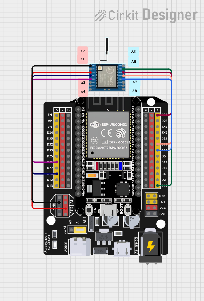
This circuit integrates an ESP32 microcontroller with a LoRa Ra-02 SX1278 module for long-range wireless communication. The ESP32's digital pins are connected to the LoRa module's SPI interface (MOSI, MISO, SCK, NSS) and control lines (RST, DI00) to enable data transmission and reception. The circuit is likely designed for IoT applications requiring low-power, wide-area network connectivity.
ESP32 and LoRa SX1278 Based Wireless Communication Module
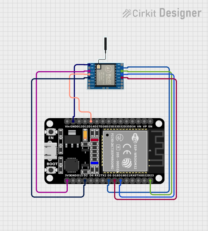
This circuit integrates an ESP32 microcontroller with a LoRa Ra-02 SX1278 module to enable long-range wireless communication. The ESP32 handles the control and data processing, while the LoRa module provides the communication link. The connections include SPI interface and control signals between the ESP32 and the LoRa module, as well as shared power and ground lines.
Wemos D1 Mini with LoRa SX1278 Communication Module
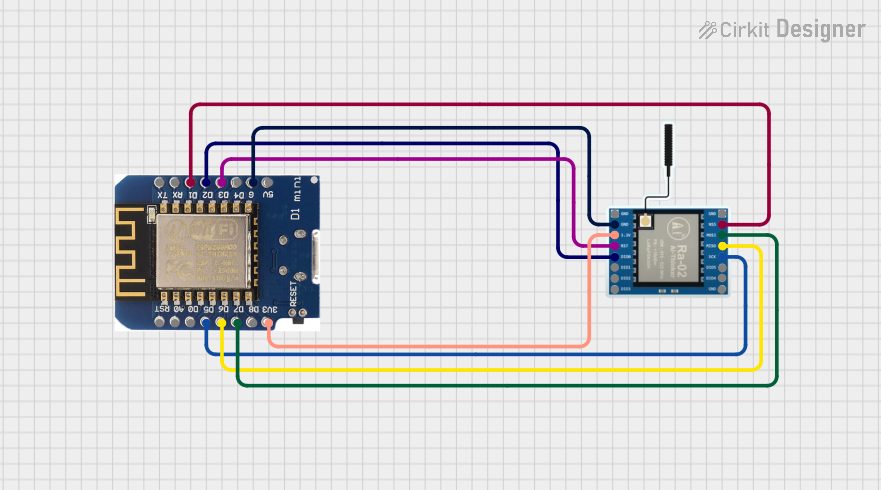
This circuit connects a Wemos D1 mini microcontroller to a LoRa Ra-02 SX1278 module for long-range wireless communication. The Wemos D1 mini's digital pins (D1, D2, D3, D5, D6, D7) are interfaced with the LoRa module's control pins (NSS, DI00, RST, SCK, MISO, MOSI) to enable SPI communication and control signals. The common ground and 3.3V power supply ensure that both components operate at the same voltage level, facilitating proper communication between them.
ESP32-Based LoRa Communication Device with OLED Display
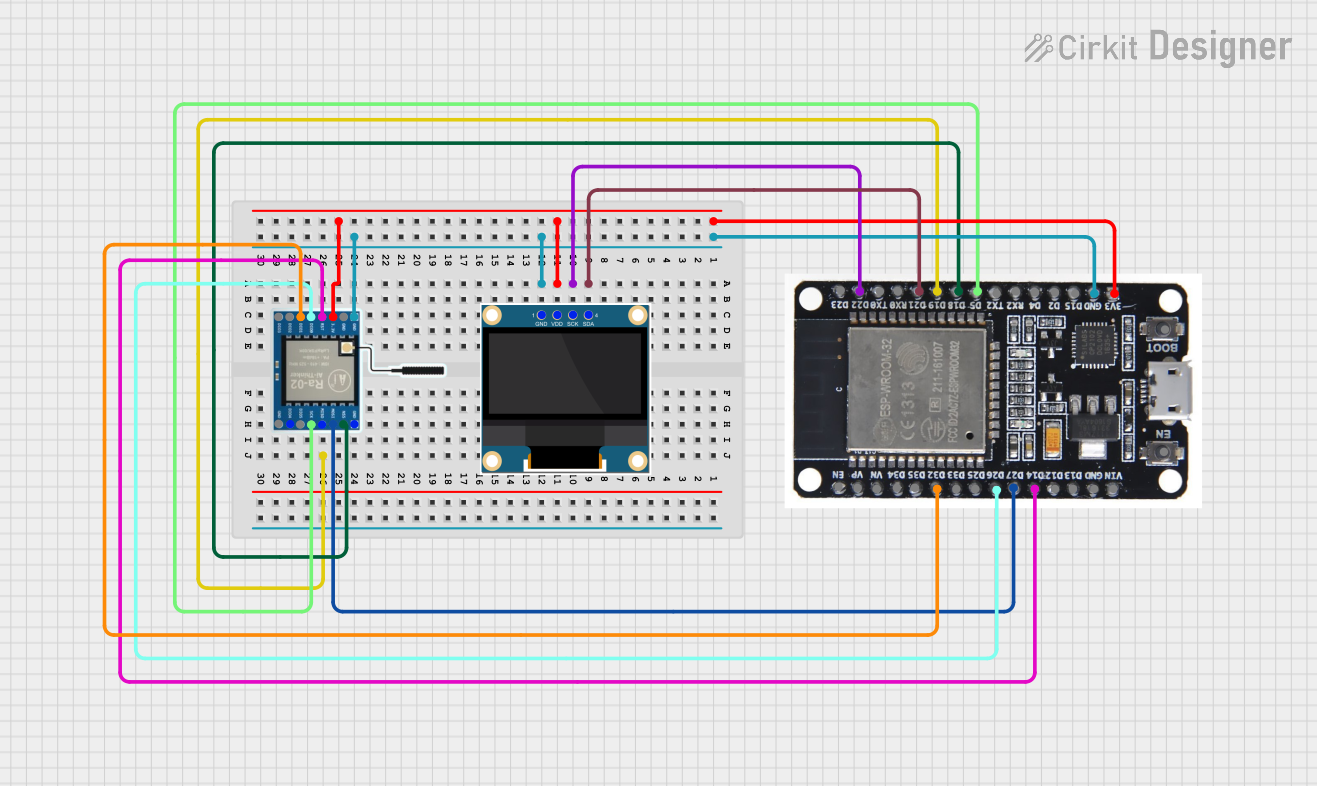
This circuit features an ESP32 microcontroller connected to a 0.96" OLED display and a LoRa Ra-02 SX1278 module for wireless communication. The ESP32 facilitates communication with the OLED display via I2C (SDA and SCK lines) and with the LoRa module via SPI (MISO, MOSI, SCK, NSS lines) and GPIO for control signals (DI00, DI01, RST). The circuit is designed for applications requiring wireless data transmission and visual data display.
Explore Projects Built with SX1278
ESP32-Based LoRa Communication Module
This circuit integrates an ESP32 microcontroller with a LoRa Ra-02 SX1278 module for long-range wireless communication. The ESP32's digital pins are connected to the LoRa module's SPI interface (MOSI, MISO, SCK, NSS) and control lines (RST, DI00) to enable data transmission and reception. The circuit is likely designed for IoT applications requiring low-power, wide-area network connectivity.
ESP32 and LoRa SX1278 Based Wireless Communication Module
This circuit integrates an ESP32 microcontroller with a LoRa Ra-02 SX1278 module to enable long-range wireless communication. The ESP32 handles the control and data processing, while the LoRa module provides the communication link. The connections include SPI interface and control signals between the ESP32 and the LoRa module, as well as shared power and ground lines.
Wemos D1 Mini with LoRa SX1278 Communication Module
This circuit connects a Wemos D1 mini microcontroller to a LoRa Ra-02 SX1278 module for long-range wireless communication. The Wemos D1 mini's digital pins (D1, D2, D3, D5, D6, D7) are interfaced with the LoRa module's control pins (NSS, DI00, RST, SCK, MISO, MOSI) to enable SPI communication and control signals. The common ground and 3.3V power supply ensure that both components operate at the same voltage level, facilitating proper communication between them.
ESP32-Based LoRa Communication Device with OLED Display
This circuit features an ESP32 microcontroller connected to a 0.96" OLED display and a LoRa Ra-02 SX1278 module for wireless communication. The ESP32 facilitates communication with the OLED display via I2C (SDA and SCK lines) and with the LoRa module via SPI (MISO, MOSI, SCK, NSS lines) and GPIO for control signals (DI00, DI01, RST). The circuit is designed for applications requiring wireless data transmission and visual data display.
Common Applications and Use Cases
- Remote control systems
- Home and industrial automation
- Wireless sensor networks
- IoT connectivity
- Smart metering
- Telemetry and remote monitoring
Technical Specifications
Key Technical Details
- Frequency Bands: 433/470/868/915 MHz
- Modulation Techniques: FSK, GFSK, MSK, GMSK, LoRa TM, and OOK
- Output Power: +20 dBm - 100 mW constant RF output vs. V supply
- Sensitivity: Down to -148 dBm
- Data Transfer Rate:
- FSK: up to 300 kbps
- LoRa: 0.018 kbps to 37.5 kbps
- Supply Voltage: 1.8 - 3.7 V
- Current Consumption: 10 mA (Rx mode), 120 mA (Tx at +20 dBm)
- Sleep Current: < 0.2 uA
- Operating Temperature Range: -40 to +85 °C
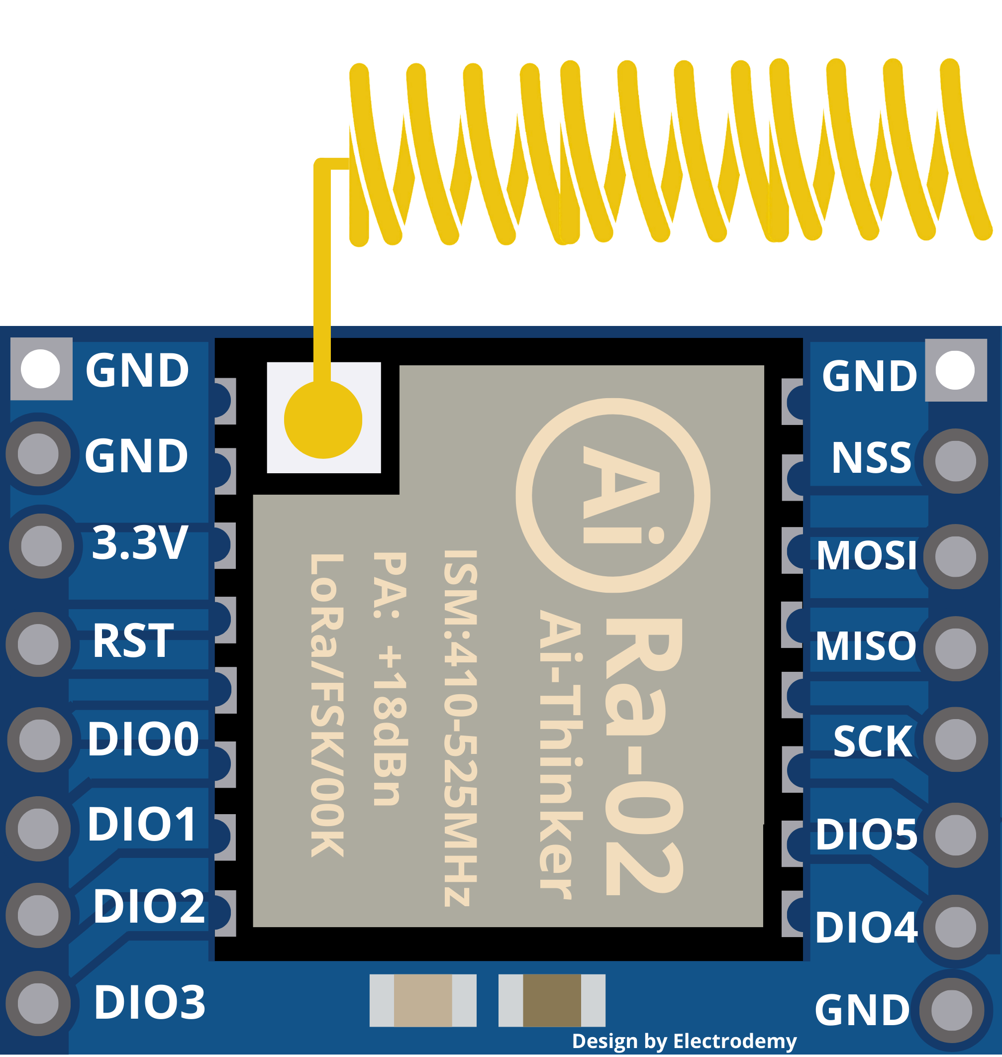
Pin Configuration and Descriptions
| Pin Number | Name | Description |
|---|---|---|
| 1 | GND | Ground connection |
| 2 | VCC | Power supply (1.8 - 3.7 V) |
| 3 | DIO0 | Digital I/O, programmable for different functions |
| 4 | DIO1 | Digital I/O, programmable for different functions |
| 5 | DIO2 | Digital I/O, programmable for different functions |
| 6 | DIO3 | Digital I/O, programmable for different functions |
| 7 | DIO4 | Digital I/O, programmable for different functions |
| 8 | DIO5 | Digital I/O, programmable for different functions |
| 9 | RST | Reset pin (active low) |
| 10 | NSS | SPI Chip Select (active low) |
| 11 | SCK | SPI Clock |
| 12 | MOSI | SPI Master Out Slave In |
| 13 | MISO | SPI Master In Slave Out |
| 14 | GND | Ground connection |
Usage Instructions
How to Use the SX1278 in a Circuit
- Power Supply: Connect the VCC pin to a power supply within the range of 1.8 - 3.7 V and ensure that the GND pins are connected to the common ground of your system.
- SPI Interface: Connect the SCK, MOSI, MISO, and NSS pins to the corresponding SPI interface pins of your microcontroller.
- Digital I/Os: Configure the DIO pins according to your application needs. These pins can be used for interrupt-driven events, such as signaling the completion of a transmission or the reception of data.
- Reset: The RST pin can be connected to a GPIO pin on your microcontroller to allow software reset of the SX1278 module.
- Antenna: Connect an appropriate antenna to the antenna pin of the SX1278 module for the specific frequency band you intend to use.
Important Considerations and Best Practices
- Ensure that the power supply is clean and within the specified voltage range to prevent damage to the SX1278.
- Use impedance-matched antennas to maximize range and comply with regulatory standards.
- Keep the RF trace and components as short as possible to minimize losses and interference.
- Follow proper ESD precautions when handling the SX1278 module to avoid electrostatic damage.
Troubleshooting and FAQs
Common Issues Users Might Face
- No Communication: Ensure that the SPI interface is correctly connected and configured. Check that the antenna is properly connected and suitable for the frequency band in use.
- Low Range: Verify that the output power settings are correct. Ensure that there are no obstructions or interference in the communication path. Check that the antenna is properly matched to the frequency band.
- High Power Consumption: Make sure that the SX1278 is in sleep mode when not transmitting or receiving to save power.
Solutions and Tips for Troubleshooting
- Double-check wiring and solder connections.
- Use a logic analyzer or oscilloscope to verify SPI communication.
- Ensure that the module's firmware is correctly configured for the desired operation mode.
- Test the module with a known good antenna and in an environment with minimal interference.
Example Code for Arduino UNO
#include <SPI.h>
#include <LoRa.h>

// Define the pins used for the SX1278
#define SS      10
#define RST     9
#define DI0     2

void setup() {
  Serial.begin(9600);
  while (!Serial);

  Serial.println("LoRa Sender");

  // Setup LoRa transceiver module with the specified pins
  LoRa.setPins(SS, RST, DI0);

  if (!LoRa.begin(915E6)) { // initialize at 915 MHz
    Serial.println("Starting LoRa failed!");
    while (1);
  }
}

void loop() {
  Serial.println("Sending packet...");

  // Send a message
  LoRa.beginPacket();
  LoRa.print("Hello, world!");
  LoRa.endPacket();

  delay(1000);
}
Note: This example assumes that the SX1278 module is connected to an Arduino UNO with the specified pin configuration. The frequency should be set according to your regional regulations and the module's capabilities.