The KPCS200 Peristaltic Pump is a robust and versatile positive displacement pump designed for the controlled dispensation of liquids. Its unique mechanism, which involves the compression and relaxation of a flexible tube by rotating rollers, ensures a contamination-free movement of fluids, as the fluid only contacts the tubing. This pump is commonly used in medical applications, chemical dosing, laboratory experiments, and food processing due to its precision and ability to handle a variety of fluids, including aggressive or sterile liquids.
Explore Projects Built with KPCS200 Peristaltic Pump
Use Cirkit Designer to design, explore, and prototype these projects online. Some projects support real-time simulation. Click "Open Project" to start designing instantly!
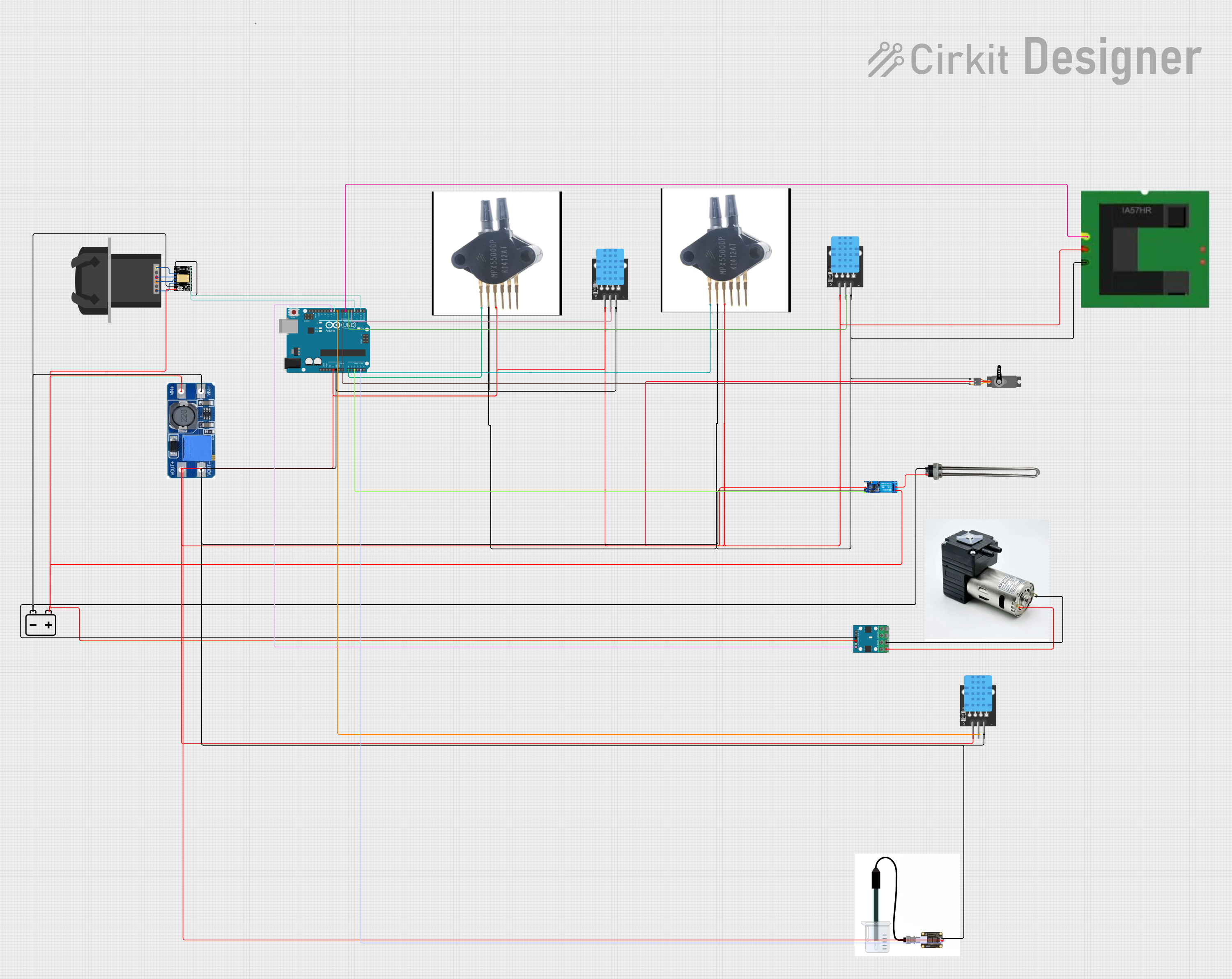
This circuit is designed to control a KPCS200 peristaltic pump using a TMC2226 stepper driver, powered by a 12V battery and regulated by a step-up boost converter. An Arduino UNO microcontroller manages various sensors, including temperature, pressure, and conductivity sensors, as well as a servo and a relay module for a water heater, enabling precise control and monitoring of fluid flow and environmental conditions.
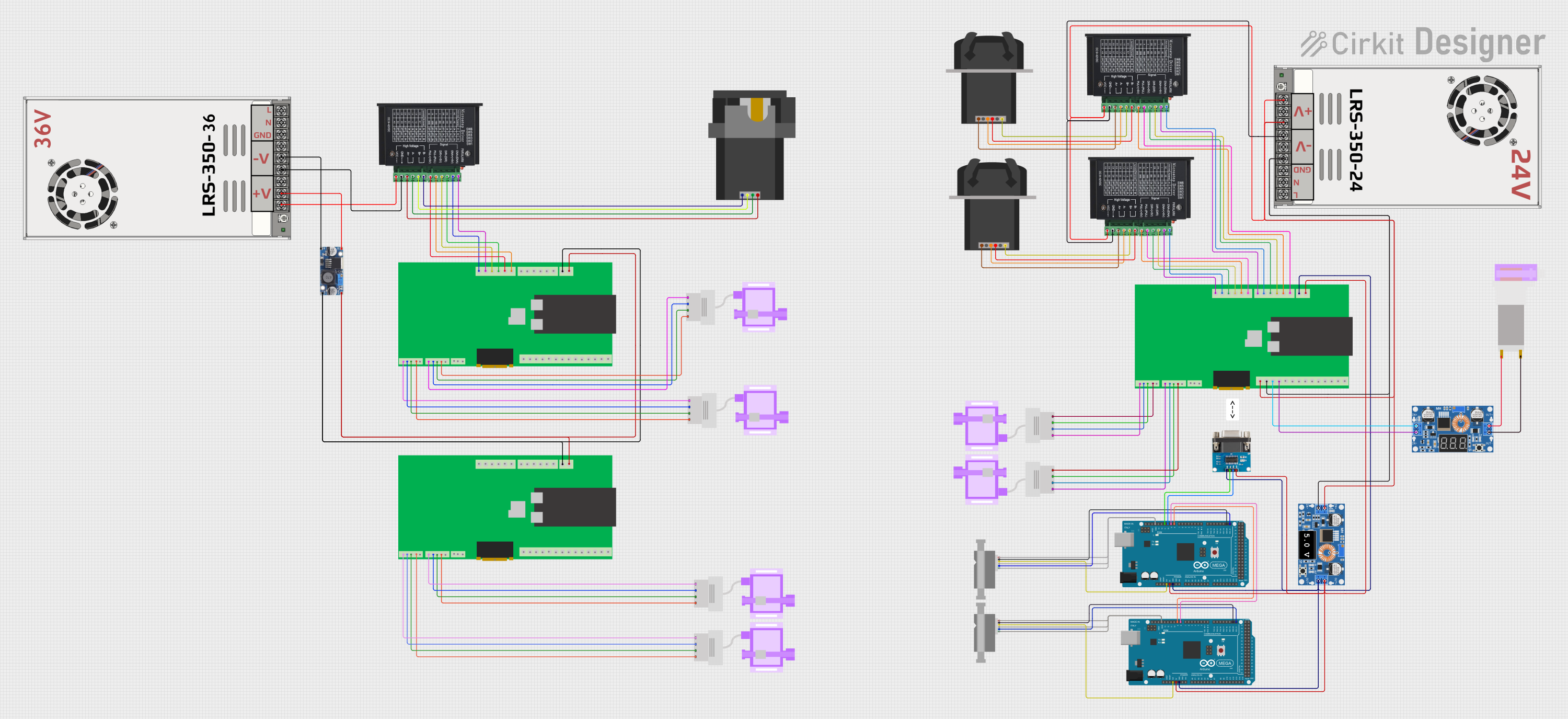
This circuit is designed for fluid control and monitoring, featuring multiple peristaltic pumps driven by TB6600 micro-stepping motor drivers, and pressure sensors interfaced with custom PCBs containing ESP32 microcontrollers. It also includes flow meters connected to Arduino Mega 2560 boards for precise flow rate measurement, with power management handled by DC-DC converters and power supplies.
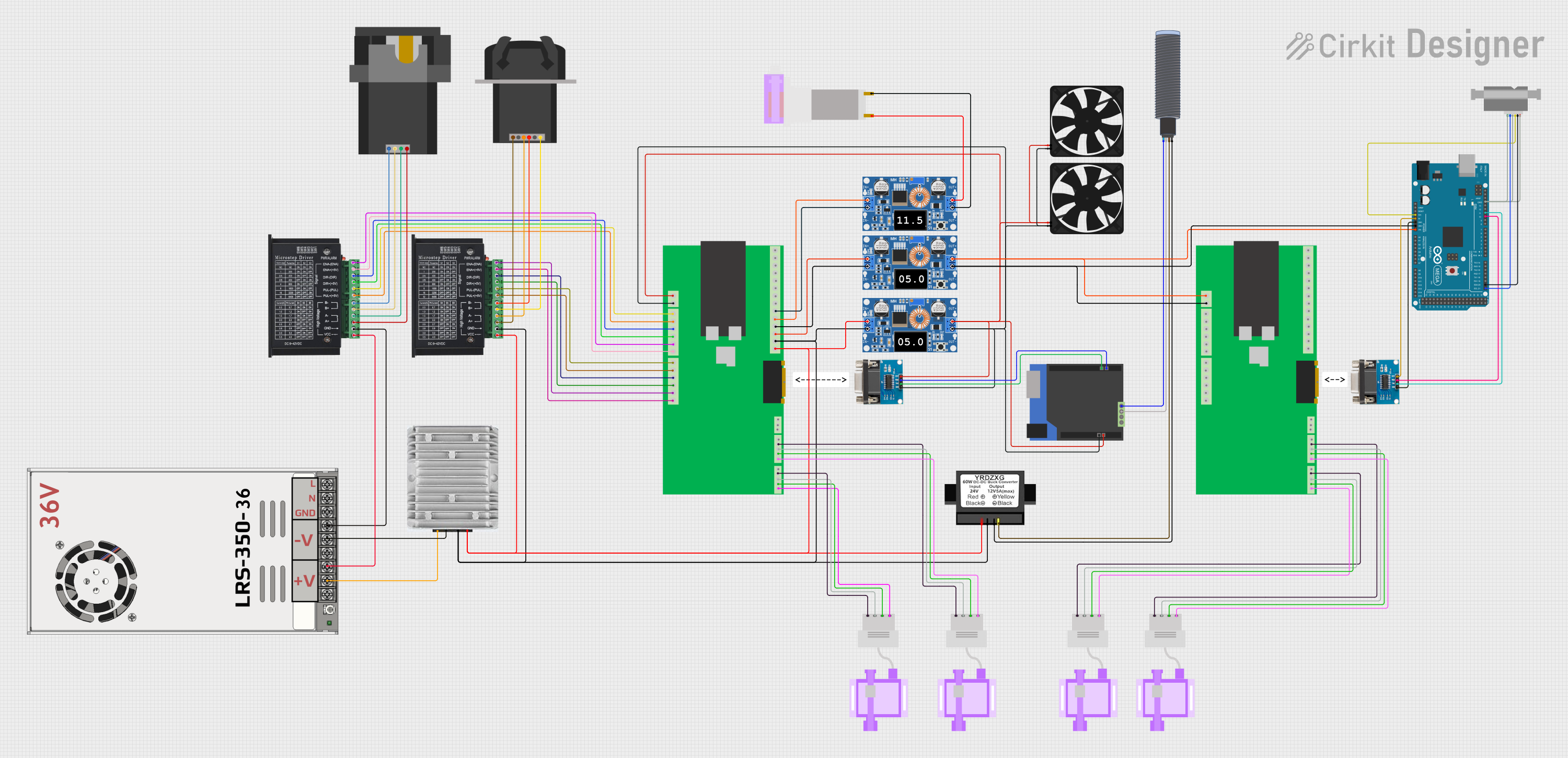
This circuit appears to be a control system for peristaltic pumps and a motor driver, with power regulation and communication capabilities. It includes a main power supply stepping down from 48V to various lower voltages for different components, two tb6600 micro stepping motor drivers controlling peristaltic pumps, and an ESP32-based custom PCB for managing signals and communication. The system also integrates an Arduino Mega for additional control and interfacing with a Sensirion flow meter, RS232 to TTL converters for serial communication, and an ultrasonic sensor for distance measurement.
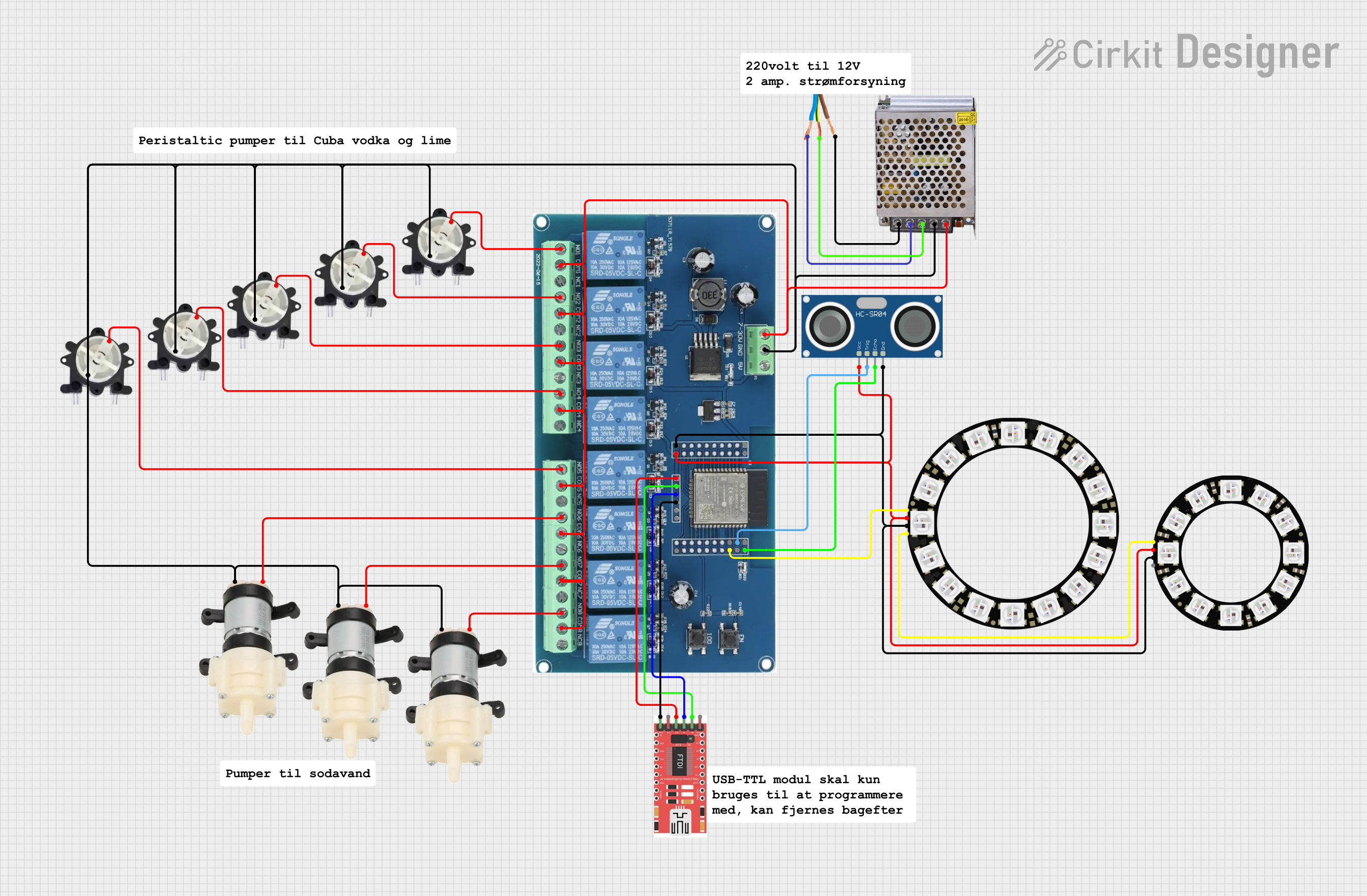
This circuit is an automated cocktail drink mixer controlled by an ESP32 microcontroller. It uses multiple peristaltic and diaphragm pumps to dispense various liquids, an ultrasonic sensor to detect the presence of a glass, and LED rings for visual feedback. The system is operated via Bluetooth commands sent from a mobile app.
Life Expectancy: > 300 hours (continuous duty cycle)
Pin Configuration and Descriptions
Pin Number
Description
Notes
1
Power (+12V DC)
Connect to positive power supply
2
Ground (GND)
Connect to power supply ground
3
Control Signal (PWM)
0-5V PWM signal for speed control
4
Direction Control
High/Low for CW/CCW rotation
5
Tachometer Output
Outputs pulses for speed feedback
Usage Instructions
Integrating with a Circuit
Power Supply: Ensure that the pump is connected to a 12V DC power supply capable of delivering sufficient current (up to 500 mA).
Control Signal: Use a PWM (Pulse Width Modulation) signal to control the speed of the pump. The duty cycle of the PWM will determine the flow rate.
Direction Control: Apply a high or low signal to the direction control pin to change the rotation direction of the pump (clockwise or counterclockwise).
Tachometer Feedback: Monitor the tachometer output to receive feedback on the pump's speed, which can be used for precise flow control.
Best Practices
Always prime the pump before use to avoid running it dry, which can damage the tubing.
Regularly inspect and replace the tubing to maintain pump performance and hygiene.
Avoid sharp bends in the tubing near the pump to prevent kinking and flow restriction.
Use a filter at the pump inlet to prevent particulate matter from entering and damaging the pump.
Example Arduino Code
// Define the control pins
const int pwmPin = 3; // PWM control signal pin
const int dirPin = 4; // Direction control pin

void setup() {
  // Set the control pins as outputs
  pinMode(pwmPin, OUTPUT);
  pinMode(dirPin, OUTPUT);

  // Start the pump at a moderate speed
  analogWrite(pwmPin, 128); // Set PWM to 50% duty cycle
  digitalWrite(dirPin, HIGH); // Set direction to clockwise
}

void loop() {
  // The pump speed can be adjusted by changing the PWM duty cycle
  // The direction can be toggled by writing HIGH or LOW to the dirPin
}
Troubleshooting and FAQs
Common Issues
Pump is not operating: Check the power supply and connections. Ensure the PWM signal is being sent to the control pin.
Flow rate is inconsistent: Inspect the tubing for wear or obstruction. Ensure the tubing is properly seated in the pump head.
Pump is noisy or vibrating excessively: This may indicate that the tubing is worn or the pump head needs cleaning.
Solutions and Tips
Power Supply Issues: Verify that the power supply is rated for 12V DC and can provide up to 500 mA of current.
Tubing Maintenance: Replace the tubing regularly to prevent degradation that can affect performance.
Flow Rate Control: Use the tachometer feedback to create a closed-loop system for precise flow rate control.
FAQs
Q: Can the KPCS200 pump handle viscous fluids?
A: Yes, but the flow rate may be reduced for very viscous fluids. Ensure the tubing is rated for the fluid's viscosity.
Q: Is the pump reversible?
A: Yes, by changing the signal on the direction control pin, you can reverse the pump's direction.
Q: How do I clean the pump?
A: Clean the external parts of the pump with a damp cloth. Do not immerse the pump in liquid. Replace the tubing for internal cleaning.
Q: What is the maximum operating temperature for the pump?
A: The pump is rated for an operating environment of 0-40°C. Avoid using it in temperatures outside this range.
This documentation provides a comprehensive guide to using the KPCS200 Peristaltic Pump. For further assistance, contact the manufacturer or refer to the detailed product manual.


 Open Project in Cirkit Designer