
How to Use ESC BLDC: Examples, Pinouts, and Specs
 Design with ESC BLDC in Cirkit Designer
Introduction
An Electronic Speed Controller (ESC) for Brushless DC (BLDC) motors is a critical component in modern motor control systems. It regulates the motor's speed, direction, and start/stop functions by varying the voltage and current supplied to the motor. ESCs are widely used in applications requiring precise motor control, such as drones, RC vehicles, robotics, and electric vehicles.
Explore Projects Built with ESC BLDC
 Open Project in Cirkit Designer
 Open Project in Cirkit Designer
 Open Project in Cirkit Designer
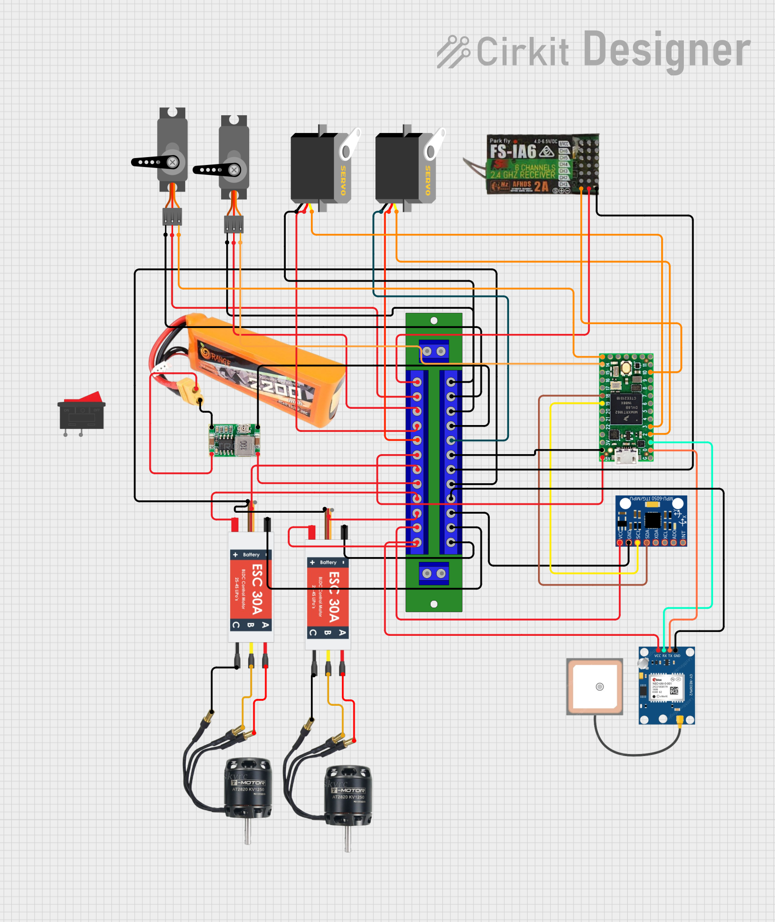 Open Project in Cirkit Designer
Explore Projects Built with ESC BLDC
Open Project in Cirkit DesignerOpen Project in Cirkit DesignerOpen Project in Cirkit DesignerOpen Project in Cirkit DesignerCommon Applications
- Drones and UAVs: For controlling the speed of propeller motors.
- RC Vehicles: To manage acceleration and braking in cars, boats, and planes.
- Robotics: For precise control of robotic arms and wheels.
- Electric Vehicles: To regulate motor speed and torque.
- Industrial Automation: For conveyor belts and other motorized systems.
Technical Specifications
Key Technical Details
| Parameter | Value/Range |
|---|---|
| Input Voltage Range | 6V to 50V (varies by model) |
| Continuous Current | 10A to 200A (model-dependent) |
| Peak Current | Up to 300A (for short durations) |
| Motor Compatibility | Brushless DC (BLDC) motors |
| Control Signal Input | PWM (Pulse Width Modulation) |
| PWM Signal Range | 1000µs to 2000µs (standard) |
| Operating Temperature | -20°C to 85°C |
| BEC Output (if available) | 5V or 6V, 2A to 5A |
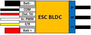
Pin Configuration and Descriptions
| Pin Name | Description |
|---|---|
| Power Input (+) | Connect to the positive terminal of the power source (e.g., battery). |
| Power Input (-) | Connect to the negative terminal of the power source (ground). |
| Motor Phase A | Connect to one of the three motor wires (phase A). |
| Motor Phase B | Connect to one of the three motor wires (phase B). |
| Motor Phase C | Connect to one of the three motor wires (phase C). |
| Signal Input | Receives PWM signal from the microcontroller or receiver. |
| Ground (GND) | Common ground for the signal input and power source. |
| BEC Output (+) | Provides regulated power for external devices (if BEC is included). |
| BEC Output (-) | Ground for the BEC output (if BEC is included). |
Usage Instructions
How to Use the ESC BLDC in a Circuit
Connect the Power Source:
- Attach the positive and negative terminals of the battery to the ESC's power input pins.
- Ensure the voltage of the power source matches the ESC's input voltage range.
Connect the Motor:
- Connect the three motor wires to the ESC's Motor Phase A, B, and C pins.
- If the motor spins in the wrong direction, swap any two of the motor wires.
Connect the Signal Input:
- Use a microcontroller (e.g., Arduino UNO) or RC receiver to send a PWM signal to the ESC's signal input pin.
- Ensure the ground of the microcontroller/receiver is connected to the ESC's ground.
Power On:
- Turn on the power source. The ESC will typically emit a series of beeps to indicate initialization.
Control the Motor:
- Send PWM signals to control the motor's speed and direction. A typical PWM range is:
- 1000µs: Motor off
- 1500µs: Motor at half speed
- 2000µs: Motor at full speed
- Send PWM signals to control the motor's speed and direction. A typical PWM range is:
Important Considerations and Best Practices
- Calibration: Some ESCs require throttle calibration before use. Follow the manufacturer's instructions.
- Cooling: Ensure proper ventilation or cooling, especially for high-current applications.
- Safety: Always test the motor in a safe environment to avoid accidents.
- Signal Quality: Use a stable and noise-free PWM signal for reliable operation.
- BEC Usage: If the ESC includes a BEC, ensure the connected devices do not exceed the BEC's current rating.
Example Code for Arduino UNO
#include <Servo.h> // Include the Servo library to generate PWM signals

Servo esc; // Create a Servo object to control the ESC

void setup() {
  esc.attach(9); // Attach the ESC signal wire to pin 9 on the Arduino
  esc.writeMicroseconds(1000); // Send minimum throttle (1000µs) to initialize
  delay(2000); // Wait for 2 seconds to allow the ESC to arm
}

void loop() {
  esc.writeMicroseconds(1500); // Set throttle to 1500µs (50% speed)
  delay(5000); // Run the motor at this speed for 5 seconds

  esc.writeMicroseconds(2000); // Set throttle to 2000µs (100% speed)
  delay(5000); // Run the motor at full speed for 5 seconds

  esc.writeMicroseconds(1000); // Stop the motor (1000µs)
  delay(5000); // Wait for 5 seconds before repeating
}
Troubleshooting and FAQs
Common Issues and Solutions
Motor Does Not Spin:
- Cause: Incorrect wiring or unarmed ESC.
- Solution: Verify all connections and ensure the ESC is armed (check the beeps).
Motor Spins in the Wrong Direction:
- Cause: Incorrect motor phase wiring.
- Solution: Swap any two motor wires to reverse the direction.
ESC Overheats:
- Cause: Excessive current draw or poor ventilation.
- Solution: Use a higher-rated ESC or improve cooling.
PWM Signal Not Detected:
- Cause: Faulty connection or incorrect signal range.
- Solution: Check the signal wire connection and ensure the PWM signal is within the ESC's range.
BEC Not Supplying Power:
- Cause: Overloaded BEC or damaged ESC.
- Solution: Reduce the load on the BEC or replace the ESC.
FAQs
Q: Can I use an ESC designed for drones in an RC car?
- A: Yes, as long as the ESC's specifications match the motor and power requirements.
Q: How do I know if my ESC has a BEC?
- A: Check the ESC's datasheet or look for additional output wires labeled as BEC.
Q: Can I control multiple ESCs with one Arduino?
- A: Yes, you can control multiple ESCs by connecting their signal wires to different PWM-capable pins on the Arduino.
Q: What happens if I exceed the ESC's current rating?
- A: The ESC may overheat, shut down, or become permanently damaged. Always use an ESC with a sufficient current rating.
This documentation provides a comprehensive guide to understanding, using, and troubleshooting an ESC for BLDC motors.