How to Use Logic Analyzer: Examples, Pinouts, and Specs
Introduction
A Logic Analyzer is a test instrument designed to capture and display multiple signals from a digital circuit or system. It enables engineers and developers to analyze the timing and logic states of digital signals, making it an essential tool for debugging, testing, and verifying digital designs.
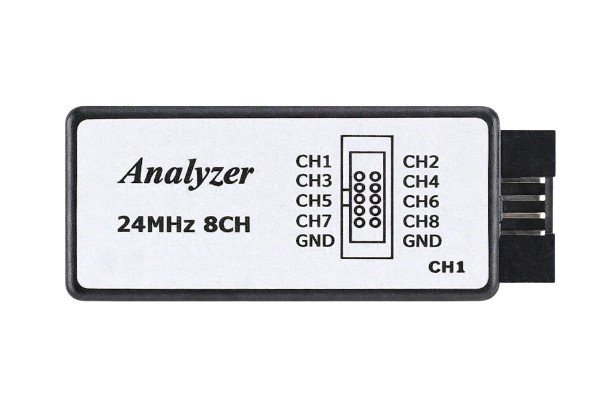
The Bộ Phân Tích Tín Hiệu Logic 8 Kênh Saleae (Manufacturer Part ID: OEM) is an 8-channel logic analyzer that provides a compact and cost-effective solution for digital signal analysis. It is widely used in embedded systems development, communication protocol debugging, and educational projects.
Explore Projects Built with Logic Analyzer
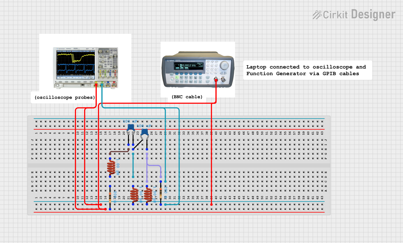
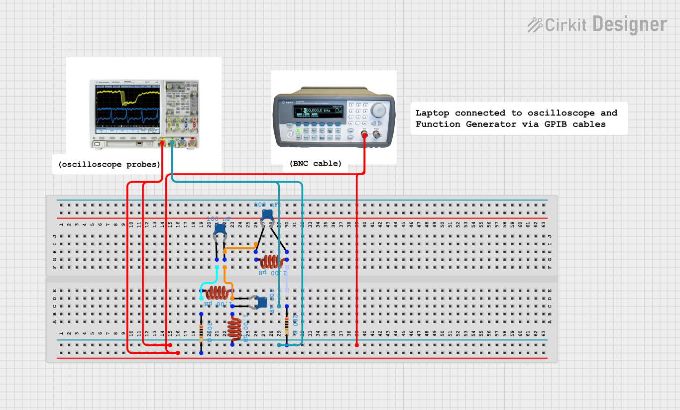
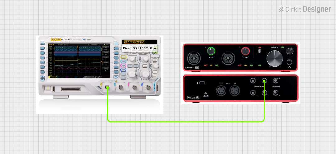

Explore Projects Built with Logic Analyzer
Common Applications:
- Debugging and testing digital circuits
- Analyzing communication protocols (e.g., I2C, SPI, UART)
- Timing analysis of digital signals
- Reverse engineering of digital systems
- Educational purposes in electronics and embedded systems
Technical Specifications
Key Technical Details:
- Manufacturer: Bộ Phân Tích Tín Hiệu Logic 8 Kênh Saleae
- Part ID: OEM
- Number of Channels: 8
- Input Voltage Range: 0V to 5.5V
- Sampling Rate: Up to 24 MHz
- Interface: USB 2.0
- Supported Protocols: I2C, SPI, UART, CAN, and more
- Operating System Compatibility: Windows, macOS, Linux
- Power Supply: Powered via USB
- Dimensions: Compact and portable design
Pin Configuration and Descriptions:
The logic analyzer has a 10-pin connector, with the following pinout:
| Pin Number | Label | Description |
|---|---|---|
| 1 | GND | Ground connection for the logic analyzer |
| 2 | CH0 | Digital input channel 0 |
| 3 | CH1 | Digital input channel 1 |
| 4 | CH2 | Digital input channel 2 |
| 5 | CH3 | Digital input channel 3 |
| 6 | CH4 | Digital input channel 4 |
| 7 | CH5 | Digital input channel 5 |
| 8 | CH6 | Digital input channel 6 |
| 9 | CH7 | Digital input channel 7 |
| 10 | NC | Not connected |
Usage Instructions
How to Use the Logic Analyzer in a Circuit:
- Connect the Ground Pin: Connect the GND pin of the logic analyzer to the ground of the circuit under test. This ensures a common reference point for signal measurements.
- Connect the Input Channels: Attach the input channels (CH0 to CH7) to the digital signals you want to analyze. Ensure the voltage levels are within the supported range (0V to 5.5V).
- Connect to a Computer: Use a USB cable to connect the logic analyzer to your computer. The device is powered via USB.
- Install Software: Download and install the compatible software (e.g., Saleae Logic software) for your operating system.
- Configure the Software:
- Select the channels you want to monitor.
- Set the sampling rate and voltage thresholds as needed.
- Choose the protocol to decode (if applicable).
- Start Capturing Data: Begin the data capture process and analyze the signals in real-time or save the data for later review.
Important Considerations and Best Practices:
- Voltage Levels: Ensure the input signals do not exceed the maximum voltage rating (5.5V) to avoid damaging the device.
- Sampling Rate: Choose a sampling rate at least 4–10 times higher than the highest frequency of the signal being analyzed for accurate results.
- Protocol Decoding: Use the software's built-in protocol analyzers to decode communication protocols like I2C, SPI, or UART.
- Signal Integrity: Minimize noise and interference by using short, high-quality wires for connections.
- Channel Usage: Use only the required number of channels to reduce clutter and simplify analysis.
Example: Using the Logic Analyzer with Arduino UNO
Below is an example of how to use the logic analyzer to monitor an I2C communication between an Arduino UNO and a sensor.
Arduino Code:
#include <Wire.h> // Include the Wire library for I2C communication

void setup() {
  Wire.begin(); // Initialize I2C as master
  Serial.begin(9600); // Start serial communication for debugging
}

void loop() {
  Wire.beginTransmission(0x68); // Start communication with device at address 0x68
  Wire.write(0x00); // Send a register address
  Wire.endTransmission(); // End the transmission

  Wire.requestFrom(0x68, 1); // Request 1 byte of data from the device
  if (Wire.available()) {
    int data = Wire.read(); // Read the received data
    Serial.println(data); // Print the data to the serial monitor
  }
  delay(1000); // Wait for 1 second before repeating
}
Steps to Analyze:
- Connect the logic analyzer's GND pin to the Arduino's GND.
- Connect CH0 to the Arduino's SDA pin and CH1 to the SCL pin.
- Open the Saleae Logic software and configure CH0 and CH1 for I2C protocol decoding.
- Start capturing data and observe the I2C communication in the software.
Troubleshooting and FAQs
Common Issues and Solutions:
No Signal Detected:
- Ensure the GND pin of the logic analyzer is connected to the circuit's ground.
- Verify that the input signals are within the supported voltage range (0V to 5.5V).
- Check the connections to the input channels.
Incorrect Protocol Decoding:
- Confirm that the correct protocol is selected in the software.
- Verify the signal integrity and ensure proper pull-up resistors are used for I2C.
Software Not Detecting the Device:
- Ensure the USB cable is properly connected.
- Check if the required drivers are installed on your computer.
- Restart the software and reconnect the device.
Noise or Unstable Signals:
- Use shorter wires to reduce noise and interference.
- Ensure a solid ground connection between the logic analyzer and the circuit.
FAQs:
Q: Can this logic analyzer decode multiple protocols simultaneously?
A: Yes, the software supports decoding multiple protocols on different channels.Q: What is the maximum sampling rate?
A: The maximum sampling rate is 24 MHz, but it may decrease if multiple channels are used simultaneously.Q: Is the device compatible with macOS?
A: Yes, the logic analyzer is compatible with Windows, macOS, and Linux.Q: Can I use this logic analyzer for analog signals?
A: No, this device is designed for digital signals only. For analog signals, use an oscilloscope.
This concludes the documentation for the Bộ Phân Tích Tín Hiệu Logic 8 Kênh Saleae logic analyzer.