How to Use CNC shield V3: Examples, Pinouts, and Specs
Introduction
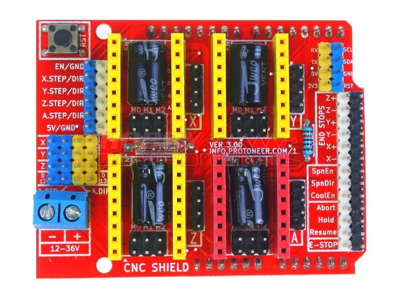
The CNC Shield V3, manufactured by Handson Technology with the part ID MDU-1008, is a versatile and powerful circuit board designed for controlling CNC machines such as 3D printers, laser cutters, and milling machines. This shield is specifically engineered to fit on top of an Arduino UNO, providing an easy-to-use platform for CNC applications. It simplifies the process of connecting multiple stepper motors and other peripherals necessary for precise machine control.
Explore Projects Built with CNC shield V3

Explore Projects Built with CNC shield V3
Common Applications and Use Cases
- 3D Printing
- Laser Engraving/Cutting
- CNC Milling
- DIY CNC projects
- Robotics
Technical Specifications
Key Technical Details
- Operating Voltage: 12-36V DC
- Stepper Motor Drivers: Supports up to 4 (typically A4988 or DRV8825)
- Input Connectors: Provision for Endstops (Limit switches)
- Compatibility: Designed to fit Arduino UNO R3 and similar boards
Pin Configuration and Descriptions
| Pin Number | Function | Description |
|---|---|---|
| A0-A5 | Endstops | Input pins for connecting limit switches |
| D8-D10 | Stepper Motor Control (X) | Control signals for the X-axis stepper motor driver |
| D2-D4 | Stepper Motor Control (Y) | Control signals for the Y-axis stepper motor driver |
| D5-D7 | Stepper Motor Control (Z) | Control signals for the Z-axis stepper motor driver |
| D12-D13 | Stepper Motor Control (A) | Optional control signals for a second Z-axis or other motor |
| GND | Ground | Common ground for logic and power |
| VIN | Voltage Input | Input voltage for the shield, passed through from Arduino UNO |
Usage Instructions
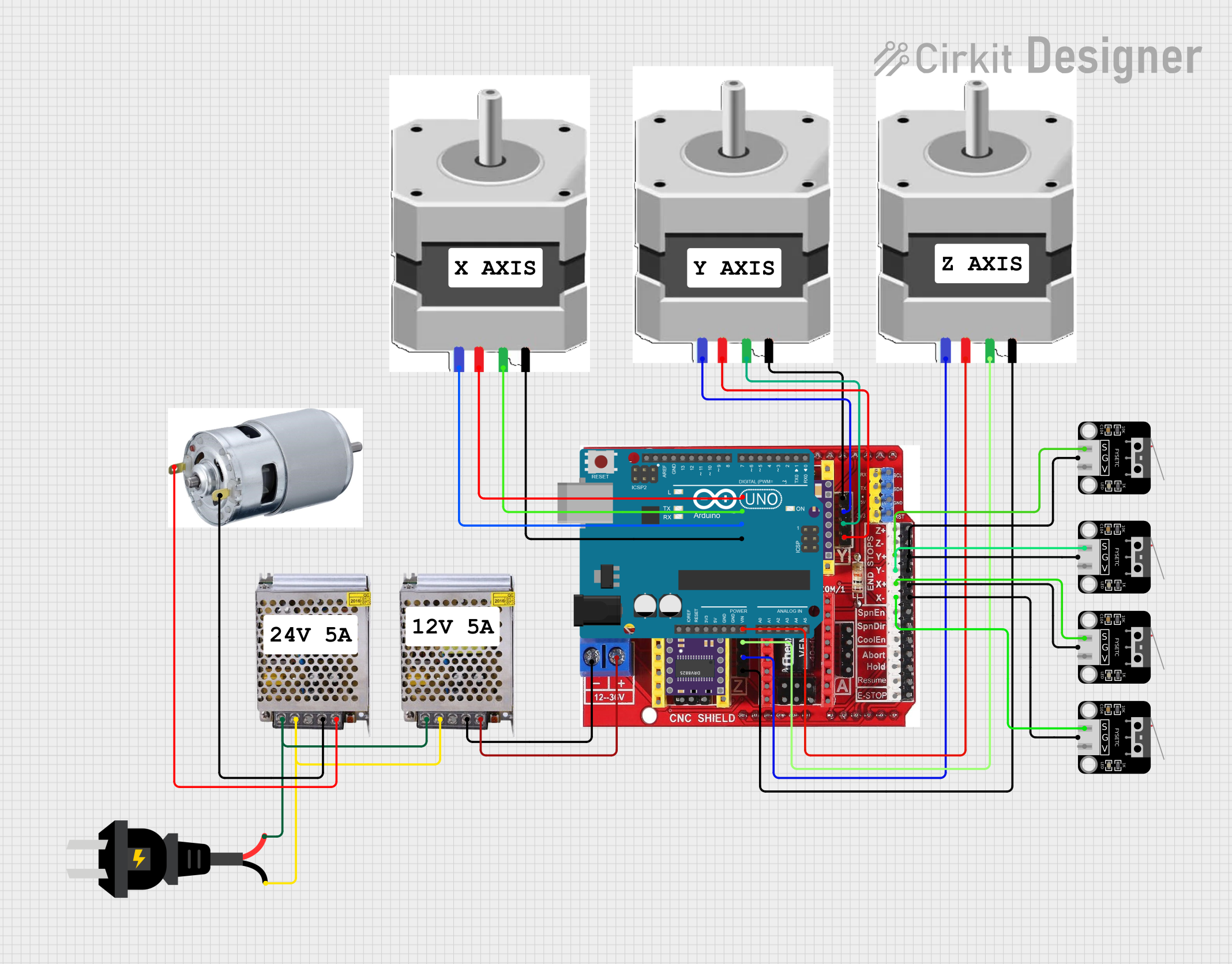
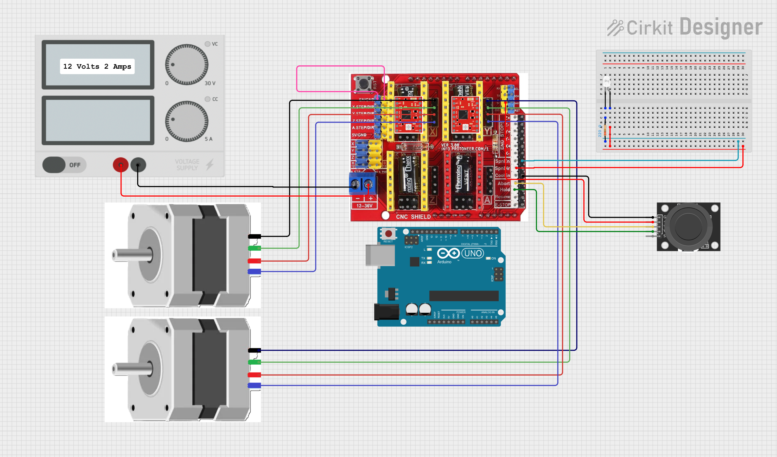
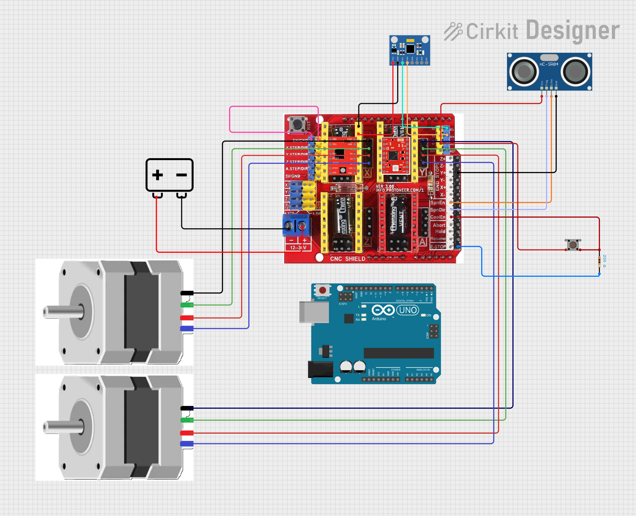
How to Use the Component in a Circuit
- Mounting the Shield: Carefully align the CNC Shield V3 pins with the headers on the Arduino UNO and press down to seat it properly.
- Installing Stepper Drivers: Insert the stepper motor drivers into their respective headers on the CNC Shield V3. Ensure they are oriented correctly according to the driver pinout.
- Connecting Stepper Motors: Connect the stepper motors to the shield using the designated headers for each axis.
- Limit Switches: Connect the limit switches to the A0-A5 pins as per the requirements of your CNC setup.
- Power Supply: Connect a suitable power supply (12-36V DC) to the VIN and GND terminals.
Important Considerations and Best Practices
- Always ensure the power supply is turned off before making or changing connections.
- Double-check the orientation of the stepper motor drivers before powering up to prevent damage.
- Use appropriate gauge wires for the power supply to handle the current without overheating.
- Configure the current limiting on the stepper motor drivers according to the specifications of your stepper motors.
- Ensure that the Arduino UNO is powered adequately, either through USB or an external power supply.
Example Code for Arduino UNO
// Basic stepper motor control for CNC Shield V3

#include <AccelStepper.h>

// Define stepper motor connections and motor interface type
#define motorInterfaceType 1
#define dirPinX 5
#define stepPinX 2
#define motorInterfaceType 1
#define dirPinY 6
#define stepPinY 3

// Create two instances of the AccelStepper class
AccelStepper stepperX(motorInterfaceType, stepPinX, dirPinX);
AccelStepper stepperY(motorInterfaceType, stepPinY, dirPinY);

void setup() {
  // Set the maximum speed and acceleration:
  stepperX.setMaxSpeed(1000);
  stepperX.setAcceleration(500);
  stepperY.setMaxSpeed(1000);
  stepperY.setAcceleration(500);
}

void loop() {
  // Set the target position for each axis
  stepperX.moveTo(1000);
  stepperY.moveTo(1000);

  // Run the motors to move to the set positions
  stepperX.run();
  stepperY.run();

  // Reset the position to zero once the target is reached
  if (stepperX.distanceToGo() == 0) {
    stepperX.setCurrentPosition(0);
  }
  if (stepperY.distanceToGo() == 0) {
    stepperY.setCurrentPosition(0);
  }
}
Troubleshooting and FAQs
Common Issues Users Might Face
- Stepper Motor Not Moving: Check the wiring and ensure that the stepper driver is correctly installed and configured.
- Erratic Motor Behavior: Verify that the power supply is adequate and the current limiting on the stepper drivers is set correctly.
- No Power to Motors: Ensure that the power supply is connected and switched on, and that the Arduino UNO is functioning properly.
Solutions and Tips for Troubleshooting
- Always start by checking connections and ensuring that all components are seated properly.
- Use a multimeter to verify the voltage at the power input and across the motor drivers.
- If a motor driver appears to be non-functional, replace it with a new one, ensuring it is inserted in the correct orientation.
- Consult the datasheets for the stepper motors and drivers for detailed specifications and configuration settings.
FAQs
Q: Can I use different types of stepper motor drivers with the CNC Shield V3? A: Yes, the CNC Shield V3 is compatible with a variety of stepper motor drivers, including A4988 and DRV8825. Ensure the drivers are compatible with the shield's pinout.
Q: How do I adjust the current for the stepper motors? A: The current can be adjusted via potentiometers on the stepper motor drivers. Consult the driver's datasheet for instructions on setting the current.
Q: What is the maximum number of stepper motors I can control with the CNC Shield V3? A: The CNC Shield V3 can control up to four stepper motors, one for each axis (X, Y, Z, and an optional second Z or another motor).
Q: Can I use the CNC Shield V3 without an Arduino UNO? A: The CNC Shield V3 is designed to interface directly with an Arduino UNO or compatible board. Using it without such a microcontroller is not recommended or supported.