How to Use ARDUINO : Examples, Pinouts, and Specs
Introduction
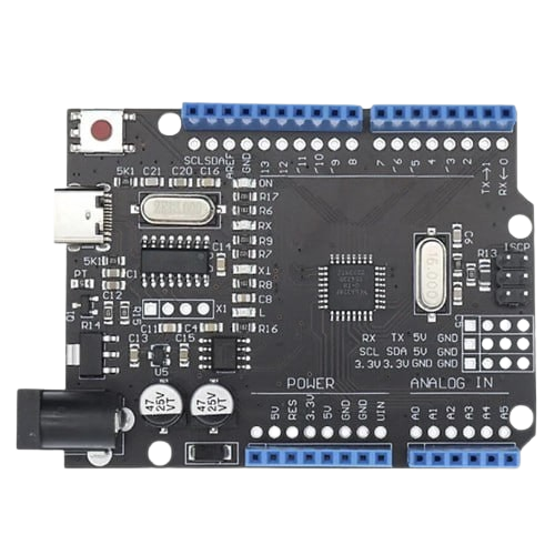
Arduino is an open-source electronics platform based on easy-to-use hardware and software. It consists of a microcontroller and a development environment for writing code to control various electronic components. Arduino boards are widely used for prototyping, educational purposes, and hobbyist projects due to their simplicity and versatility.
Explore Projects Built with ARDUINO
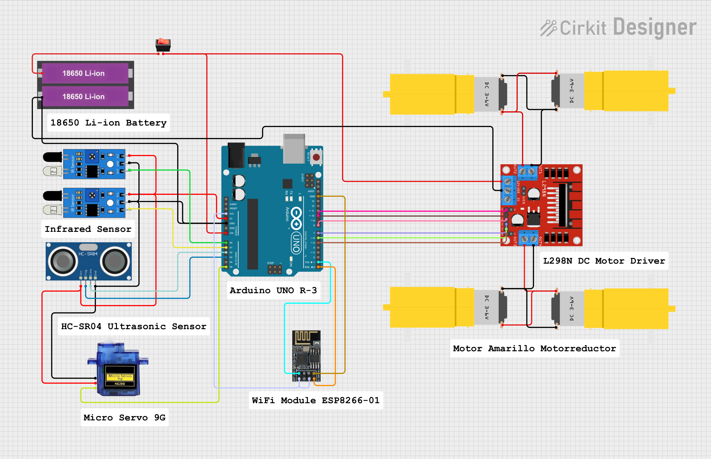
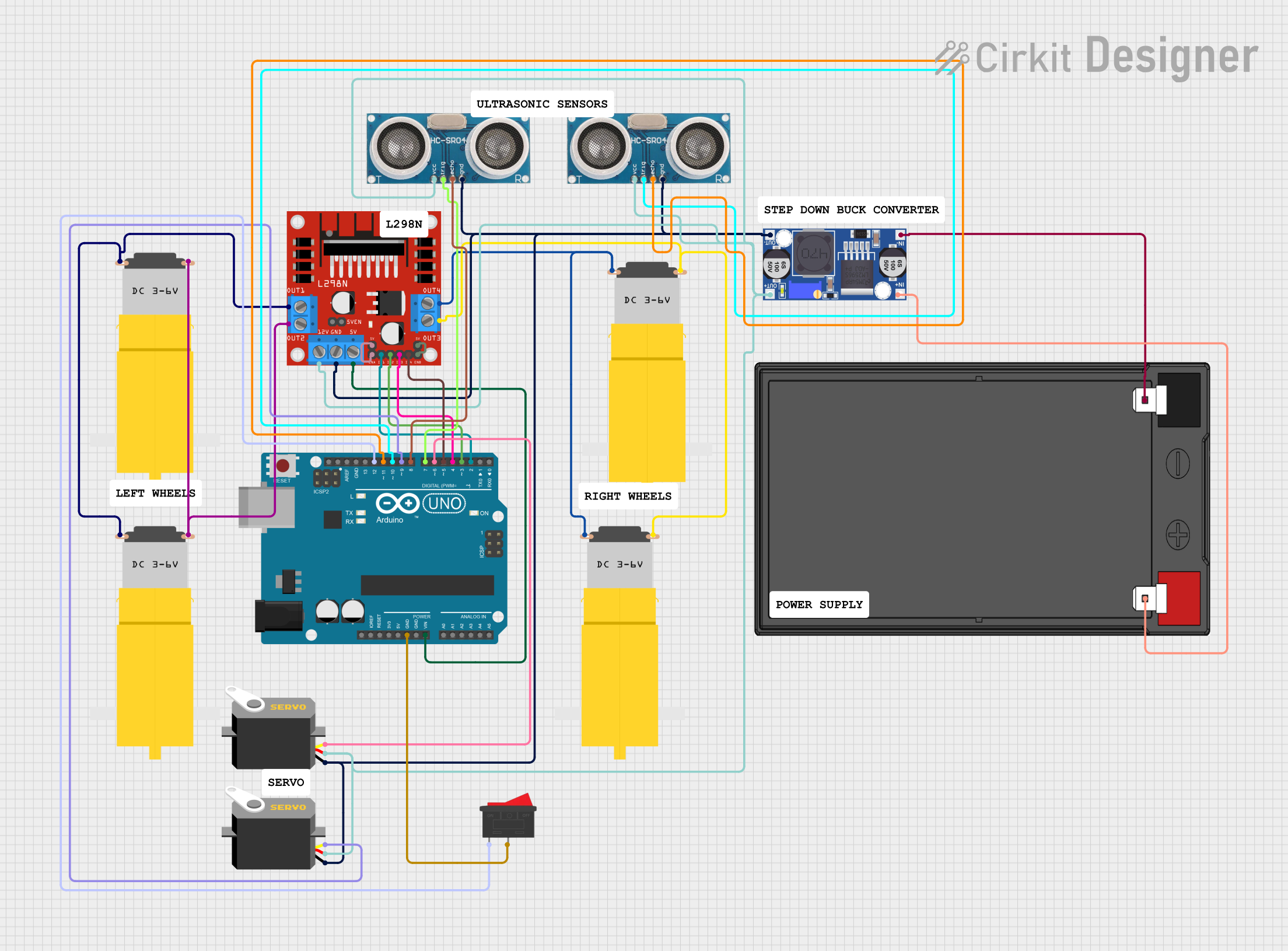
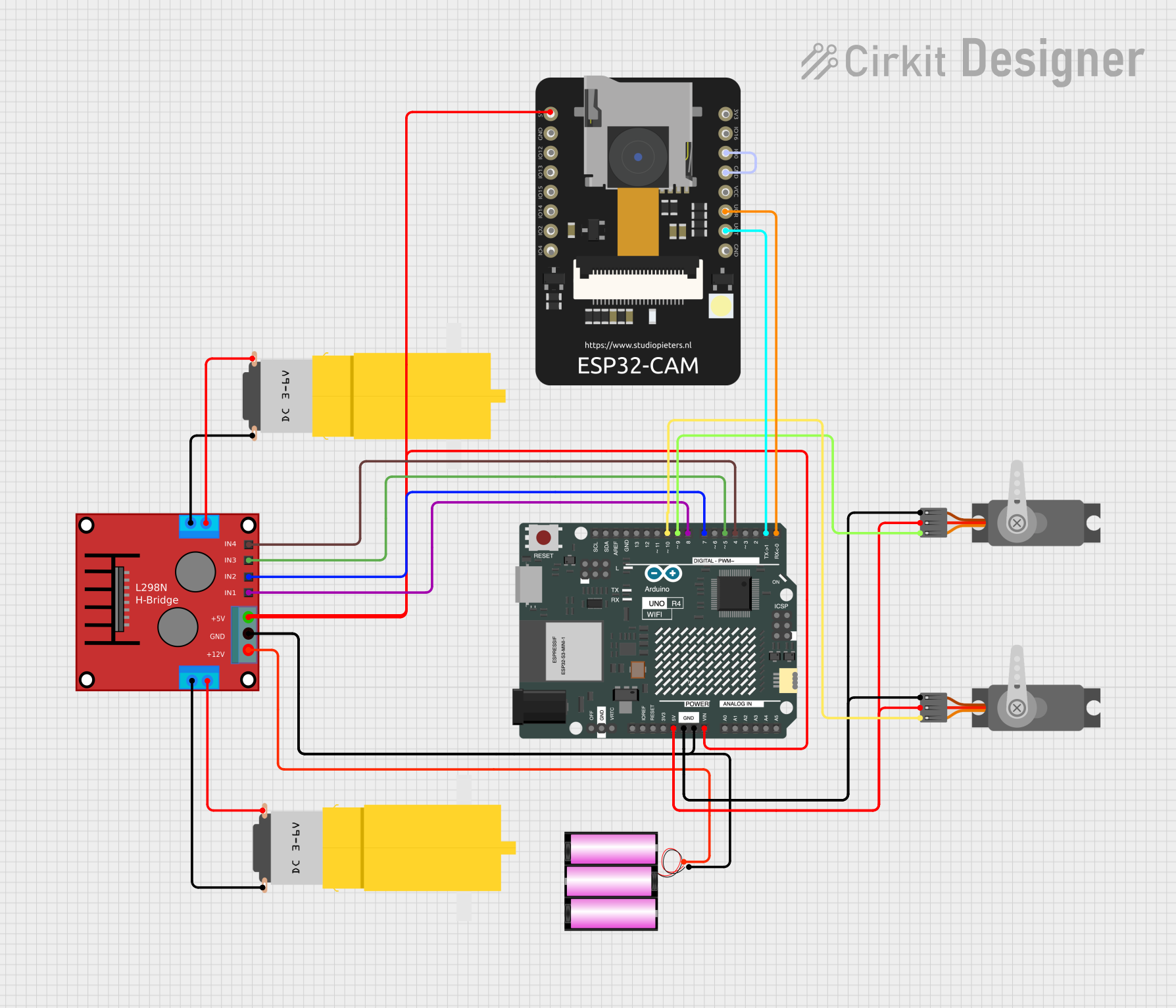
Explore Projects Built with ARDUINO
Common Applications and Use Cases
- Prototyping IoT (Internet of Things) devices
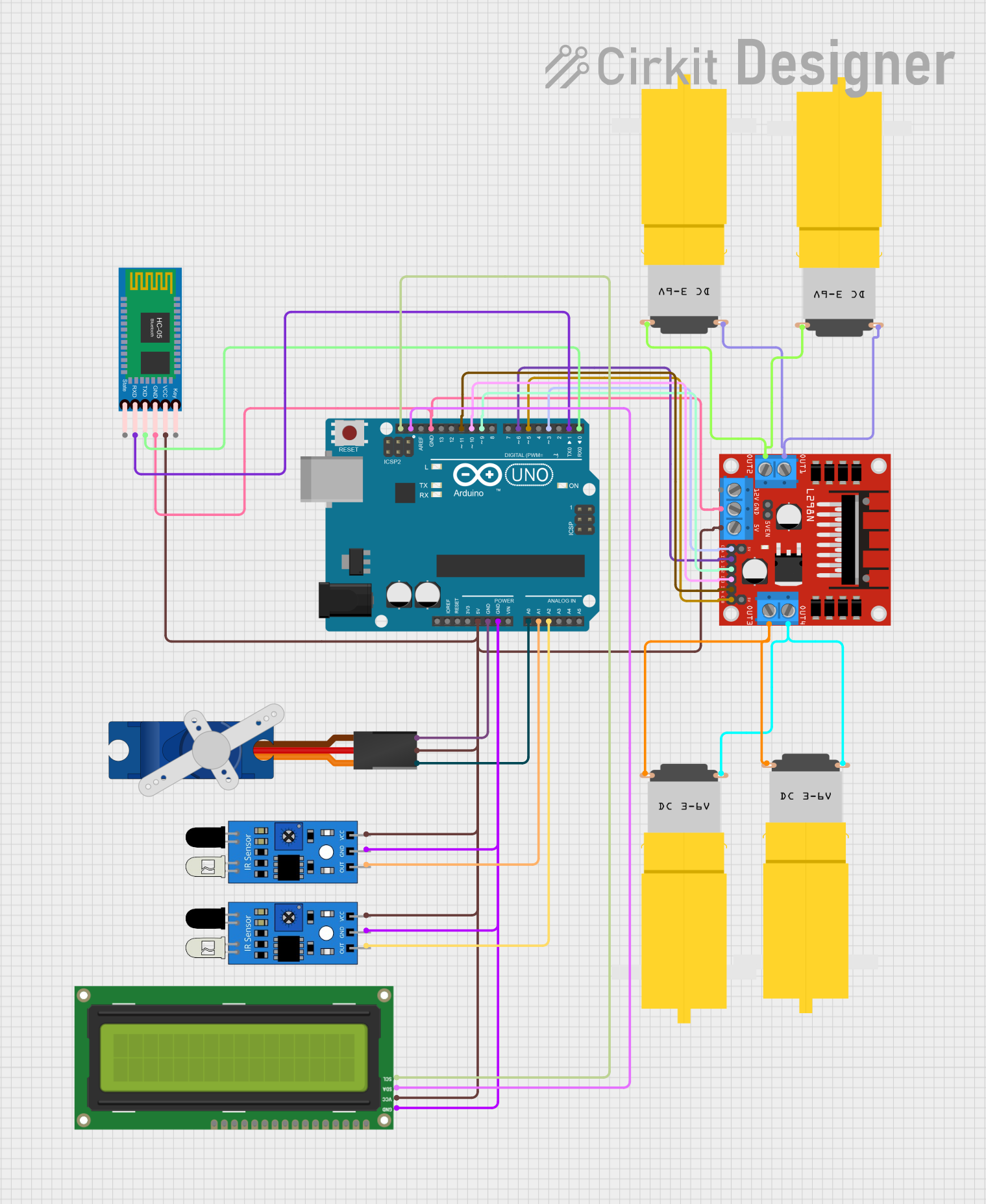
- Robotics and automation projects
- Sensor data acquisition and processing
- Home automation systems
- Educational tools for learning programming and electronics
- Wearable technology and interactive art installations
Technical Specifications
Below are the general technical specifications for a typical Arduino board, such as the Arduino UNO:
Key Technical Details
- Microcontroller: ATmega328P (for Arduino UNO)
- Operating Voltage: 5V
- Input Voltage (recommended): 7-12V
- Input Voltage (limit): 6-20V
- Digital I/O Pins: 14 (6 of which provide PWM output)
- Analog Input Pins: 6
- DC Current per I/O Pin: 20 mA
- Flash Memory: 32 KB (0.5 KB used by bootloader)
- SRAM: 2 KB
- EEPROM: 1 KB
- Clock Speed: 16 MHz
- USB Connection: Type-B USB
- Dimensions: 68.6 mm x 53.4 mm
Pin Configuration and Descriptions
The Arduino UNO has a total of 28 pins, which are categorized as follows:
| Pin | Type | Description |
|---|---|---|
| 0-13 | Digital I/O | General-purpose digital input/output pins. Pins 3, 5, 6, 9, 10, and 11 support PWM. |
| A0-A5 | Analog Input | Analog input pins for reading sensor data (0-5V). |
| GND | Ground | Ground connection. |
| 5V | Power Output | Provides 5V power to external components. |
| 3.3V | Power Output | Provides 3.3V power to external components. |
| VIN | Power Input | Input voltage to the Arduino when using an external power source (7-12V). |
| RESET | Reset | Resets the microcontroller. |
| TX/RX | Serial I/O | Transmit (TX) and Receive (RX) pins for serial communication. |
| ICSP | Programming Pins | Used for in-circuit serial programming of the microcontroller. |
Usage Instructions
How to Use the Arduino in a Circuit
- Power the Arduino: Connect the Arduino to your computer via USB or use an external power supply (7-12V).
- Connect Components: Attach sensors, actuators, or other components to the appropriate pins.
- Write Code: Use the Arduino IDE to write a program (sketch) to control the connected components.
- Upload Code: Upload the sketch to the Arduino board using the USB connection.
- Run the Circuit: Once the code is uploaded, the Arduino will execute the program and interact with the connected components.
Important Considerations and Best Practices
- Always check the voltage and current ratings of connected components to avoid damage.
- Use resistors with LEDs to limit current and prevent burnout.
- Avoid drawing more than 20 mA from any single I/O pin.
- Use external power sources for high-power components like motors or relays.
- Ensure proper grounding between the Arduino and external components.
Example: Blinking an LED with Arduino UNO
Below is an example code to blink an LED connected to pin 13:
// This program blinks an LED connected to pin 13 of the Arduino UNO.
// The LED will turn on for 1 second and off for 1 second in a loop.

void setup() {
  pinMode(13, OUTPUT); // Set pin 13 as an output pin
}

void loop() {
  digitalWrite(13, HIGH); // Turn the LED on
  delay(1000);            // Wait for 1 second
  digitalWrite(13, LOW);  // Turn the LED off
  delay(1000);            // Wait for 1 second
}
Troubleshooting and FAQs
Common Issues and Solutions
Arduino Not Detected by Computer:
- Ensure the USB cable is properly connected.
- Check if the correct COM port is selected in the Arduino IDE.
- Install or update the USB drivers for the Arduino board.
Code Upload Fails:
- Verify that the correct board and port are selected in the Arduino IDE.
- Press the reset button on the Arduino before uploading the code.
- Check for loose or incorrect connections that might interfere with the upload process.
Components Not Working as Expected:
- Double-check the wiring and connections.
- Ensure the components are compatible with the Arduino's voltage and current ratings.
- Use a multimeter to test the components and connections.
Arduino Overheating:
- Avoid drawing excessive current from the board.
- Use external power sources for high-power components.
FAQs
Q: Can I power the Arduino with a battery?
A: Yes, you can use a 9V battery connected to the VIN pin or the DC power jack.Q: Can I use the Arduino to control a motor?
A: Yes, but you should use a motor driver or transistor circuit to handle the motor's higher current requirements.Q: What is the maximum current the Arduino can supply?
A: The 5V pin can supply up to 500 mA when powered via USB, but individual I/O pins are limited to 20 mA each.Q: Can I use multiple sensors with the Arduino?
A: Yes, you can connect multiple sensors to the analog and digital pins, but ensure the total current draw does not exceed the board's limits.