How to Use SPI Camera : Examples, Pinouts, and Specs
Introduction
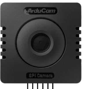
The Arducam Mega OV5642 SPI Camera is a versatile camera module designed for seamless integration with microcontrollers and embedded systems. It utilizes the Serial Peripheral Interface (SPI) protocol for high-speed data transfer, making it an excellent choice for applications requiring efficient image capture and processing. The OV5642 sensor supports resolutions up to 5 megapixels, providing high-quality images for a variety of use cases.
Explore Projects Built with SPI Camera
Explore Projects Built with SPI Camera
Common Applications and Use Cases
- IoT and Smart Devices: Used in home automation systems, security cameras, and smart doorbells.
- Robotics: Enables vision-based navigation and object detection.
- Embedded Systems: Ideal for image processing and machine learning applications.
- Prototyping and Development: Frequently used with microcontrollers like Arduino, ESP32, and Raspberry Pi for rapid prototyping.
Technical Specifications
The following table outlines the key technical details of the Arducam Mega OV5642 SPI Camera:
| Parameter | Value |
|---|---|
| Sensor Model | OV5642 |
| Resolution | Up to 5 MP (2592 x 1944 pixels) |
| Interface | SPI |
| Operating Voltage | 3.3V |
| Power Consumption | ~120mA (active mode) |
| Lens Type | Fixed focus |
| Field of View (FOV) | 60° (default lens) |
| Image Format | JPEG, RAW, RGB565, YUV422 |
| Frame Rate | Up to 15 fps (at full resolution) |
| Operating Temperature | -20°C to 70°C |
Pin Configuration and Descriptions
The SPI Camera module has the following pinout:
| Pin Name | Pin Number | Description |
|---|---|---|
| VCC | 1 | Power supply input (3.3V). |
| GND | 2 | Ground connection. |
| SCK | 3 | SPI clock input. |
| MOSI | 4 | SPI Master Out Slave In (data input to the camera). |
| MISO | 5 | SPI Master In Slave Out (data output from the camera). |
| CS | 6 | Chip Select (active low, used to enable communication with the camera). |
| RESET | 7 | Reset pin (active low, used to reset the camera module). |
| PWDN | 8 | Power-down mode pin (active high, used to reduce power consumption). |
Usage Instructions
How to Use the Component in a Circuit
- Power Supply: Connect the VCC pin to a 3.3V power source and the GND pin to ground.
- SPI Connections:
- Connect the SCK, MOSI, and MISO pins to the corresponding SPI pins on your microcontroller.
- Use the CS pin to select the camera module during SPI communication.
- Control Pins:
- Connect the RESET pin to a GPIO pin on your microcontroller for resetting the module.
- Optionally, connect the PWDN pin to a GPIO pin to enable power-down functionality.
- Software Setup:
- Install the Arducam library for your microcontroller platform (e.g., Arduino IDE).
- Configure the SPI settings (clock speed, mode, etc.) as per the camera's requirements.
Important Considerations and Best Practices
- Voltage Levels: Ensure all GPIO pins interfacing with the camera operate at 3.3V logic levels to avoid damage.
- SPI Clock Speed: Use an SPI clock speed of up to 8 MHz for reliable communication.
- Lens Adjustment: The default lens is fixed focus; ensure the object is within the focus range for clear images.
- Power Consumption: Use the PWDN pin to reduce power consumption when the camera is idle.
Example Code for Arduino UNO
Below is an example of how to interface the SPI Camera with an Arduino UNO:
#include <ArduCAM.h>
#include <Wire.h>
#include <SPI.h>

// Define the camera model
#define OV5642_CAM
ArduCAM myCAM(OV5642, 10); // CS pin connected to pin 10 on Arduino

void setup() {
  Serial.begin(115200);
  Wire.begin();
  SPI.begin();

  // Initialize the camera
  pinMode(10, OUTPUT); // Set CS pin as output
  digitalWrite(10, HIGH); // Deselect the camera
  myCAM.initCAM();

  // Test camera connection
  uint8_t vid, pid;
  myCAM.wrSensorReg8_8(0xff, 0x01); // Select sensor register bank
  myCAM.rdSensorReg8_8(0x0A, &vid); // Read sensor ID
  myCAM.rdSensorReg8_8(0x0B, &pid);

  if (vid == 0x56 && pid == 0x42) {
    Serial.println("Camera detected successfully!");
  } else {
    Serial.println("Camera not detected. Check connections.");
  }
}

void loop() {
  // Capture an image
  myCAM.flushFIFO();
  myCAM.startCapture();

  while (!myCAM.getBit(ARDUCHIP_TRIG, CAP_DONE_MASK)) {
    // Wait for capture to complete
  }

  Serial.println("Image captured!");
  // Add code here to read and process the image data
}
Troubleshooting and FAQs
Common Issues and Solutions
Camera Not Detected:
- Cause: Incorrect wiring or insufficient power supply.
- Solution: Double-check all connections and ensure the VCC pin is receiving 3.3V.
Blurry Images:
- Cause: Object is outside the focus range of the fixed-focus lens.
- Solution: Adjust the distance between the camera and the object.
No Image Data:
- Cause: SPI communication failure.
- Solution: Verify SPI connections and ensure the CS pin is correctly configured.
High Power Consumption:
- Cause: Camera remains active when not in use.
- Solution: Use the PWDN pin to enable power-down mode when the camera is idle.
FAQs
Can this camera work with 5V microcontrollers?
- Yes, but you must use a level shifter to convert 5V logic to 3.3V.
What is the maximum SPI clock speed supported?
- The camera supports SPI clock speeds up to 8 MHz.
Can I use this camera for video streaming?
- While possible, the frame rate and resolution may be limited by the SPI bandwidth.
Is the lens replaceable?
- Yes, the lens can be replaced with compatible M12 lenses for different FOVs.