How to Use GOOUUU-ESP32-C3: Examples, Pinouts, and Specs
Introduction
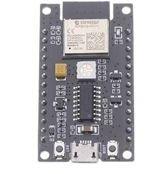
The GOOUUU-ESP32-C3 is a compact, low-power microcontroller board built around the ESP32-C3 chip. It features integrated Wi-Fi and Bluetooth Low Energy (BLE) connectivity, making it an excellent choice for Internet of Things (IoT) applications. This board is designed to support a wide range of sensors and peripherals, offering versatile GPIO pins, ADCs, and other interfaces. Its small form factor and energy efficiency make it ideal for smart home devices, wearables, and industrial IoT solutions.
Explore Projects Built with GOOUUU-ESP32-C3

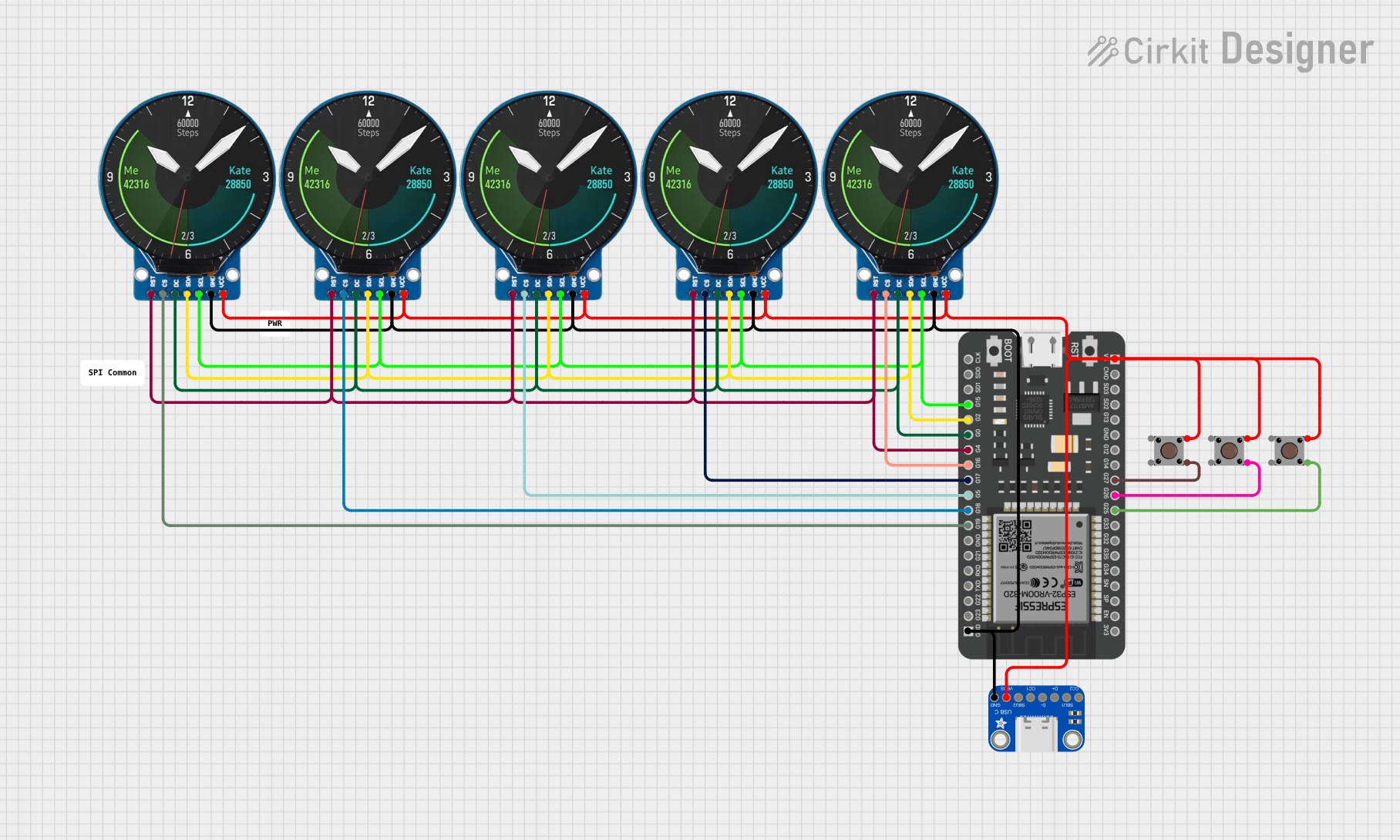


Explore Projects Built with GOOUUU-ESP32-C3
Common Applications and Use Cases
- Smart home automation (e.g., lighting, thermostats, security systems)
- Wearable devices and health monitoring
- Industrial IoT (e.g., sensor networks, predictive maintenance)
- Wireless data logging and monitoring
- Prototyping and development of connected devices
Technical Specifications
The GOOUUU-ESP32-C3 offers the following key technical features:
| Specification | Details |
|---|---|
| Microcontroller | ESP32-C3 (RISC-V 32-bit single-core processor) |
| Clock Speed | Up to 160 MHz |
| Flash Memory | 4 MB |
| SRAM | 400 KB |
| Connectivity | Wi-Fi 802.11 b/g/n (2.4 GHz), Bluetooth 5.0 LE |
| GPIO Pins | 22 GPIO pins |
| ADC Channels | 6 (12-bit resolution) |
| Operating Voltage | 3.3V |
| Input Voltage Range | 5V (via USB) |
| Power Consumption | Ultra-low power modes available |
| Interfaces | UART, SPI, I2C, PWM, ADC, DAC |
| Dimensions | 18 mm x 25 mm |
Pin Configuration and Descriptions
The GOOUUU-ESP32-C3 has a total of 22 GPIO pins, which can be configured for various functions. Below is the pinout description:
| Pin | Name | Function |
|---|---|---|
| 1 | GND | Ground |
| 2 | 3V3 | 3.3V power output |
| 3 | EN | Enable pin (active high) |
| 4 | GPIO0 | General-purpose I/O, boot mode selection |
| 5 | GPIO1 | General-purpose I/O, UART TX |
| 6 | GPIO2 | General-purpose I/O, UART RX |
| 7 | GPIO3 | General-purpose I/O, ADC channel |
| 8 | GPIO4 | General-purpose I/O, PWM output |
| 9 | GPIO5 | General-purpose I/O, SPI MOSI |
| 10 | GPIO6 | General-purpose I/O, SPI MISO |
| 11 | GPIO7 | General-purpose I/O, SPI CLK |
| 12 | GPIO8 | General-purpose I/O, I2C SDA |
| 13 | GPIO9 | General-purpose I/O, I2C SCL |
| 14 | GPIO10 | General-purpose I/O, ADC channel |
| 15 | GPIO11 | General-purpose I/O, PWM output |
| 16 | GPIO12 | General-purpose I/O, ADC channel |
| 17 | GPIO13 | General-purpose I/O, UART TX |
| 18 | GPIO14 | General-purpose I/O, UART RX |
| 19 | GPIO15 | General-purpose I/O, ADC channel |
| 20 | GPIO16 | General-purpose I/O, PWM output |
| 21 | GPIO17 | General-purpose I/O, ADC channel |
| 22 | GPIO18 | General-purpose I/O, ADC channel |
Usage Instructions
How to Use the GOOUUU-ESP32-C3 in a Circuit
Powering the Board:
- Connect the board to a 5V power source via the USB-C port. The onboard voltage regulator will step down the voltage to 3.3V.
- Alternatively, supply 3.3V directly to the 3V3 pin.
Programming the Board:
- Use the Arduino IDE or ESP-IDF (Espressif IoT Development Framework) to program the board.
- Select "ESP32-C3 Dev Module" as the board in the Arduino IDE.
Connecting Peripherals:
- Use the GPIO pins to connect sensors, actuators, or other peripherals.
- Ensure that the voltage levels of connected devices are compatible with the 3.3V logic of the board.
Wi-Fi and Bluetooth Setup:
- Use the built-in libraries (e.g.,
WiFi.handBLEDevice.hin Arduino) to configure wireless connectivity.
- Use the built-in libraries (e.g.,
Important Considerations and Best Practices
- Avoid supplying voltages higher than 3.3V to the GPIO pins to prevent damage.
- Use pull-up or pull-down resistors as needed for input pins.
- When using ADC channels, ensure the input voltage does not exceed 3.3V.
- For low-power applications, utilize the deep sleep mode to conserve energy.
Example Code for Arduino UNO Integration
Below is an example of how to use the GOOUUU-ESP32-C3 to read a temperature sensor and send the data over Wi-Fi:
#include <WiFi.h> // Include Wi-Fi library

// Wi-Fi credentials
const char* ssid = "Your_SSID";
const char* password = "Your_PASSWORD";

// Pin configuration
const int tempSensorPin = 34; // ADC pin connected to the temperature sensor

void setup() {
  Serial.begin(115200); // Initialize serial communication
  WiFi.begin(ssid, password); // Connect to Wi-Fi

  // Wait for Wi-Fi connection
  while (WiFi.status() != WL_CONNECTED) {
    delay(1000);
    Serial.println("Connecting to Wi-Fi...");
  }
  Serial.println("Connected to Wi-Fi!");
}

void loop() {
  // Read temperature sensor value
  int sensorValue = analogRead(tempSensorPin);

  // Convert sensor value to voltage (assuming 3.3V reference)
  float voltage = sensorValue * (3.3 / 4095.0);

  // Print the voltage to the serial monitor
  Serial.print("Sensor Voltage: ");
  Serial.println(voltage);

  delay(1000); // Wait 1 second before the next reading
}
Troubleshooting and FAQs
Common Issues and Solutions
The board is not detected by the computer:
- Ensure the USB cable is functional and supports data transfer.
- Install the necessary USB-to-serial drivers for the ESP32-C3.
Wi-Fi connection fails:
- Double-check the SSID and password.
- Ensure the Wi-Fi network is operating on the 2.4 GHz band (not 5 GHz).
GPIO pins are not functioning as expected:
- Verify the pin configuration in your code.
- Check for conflicting pin assignments.
The board overheats:
- Ensure the input voltage does not exceed 5V.
- Avoid drawing excessive current from the GPIO pins.
FAQs
Can I use 5V sensors with the GOOUUU-ESP32-C3?
No, the GPIO pins operate at 3.3V logic. Use a level shifter for 5V sensors.What is the maximum Wi-Fi range?
The range depends on environmental factors but typically extends up to 50 meters indoors.Does the board support OTA (Over-the-Air) updates?
Yes, the ESP32-C3 supports OTA updates for firmware.Can I use the board with batteries?
Yes, you can power the board with a 3.7V LiPo battery connected to the 3V3 pin, but ensure proper regulation.