How to Use Adafruit Mini 8x8 LED Matrix Backpack Blue: Examples, Pinouts, and Specs
Introduction
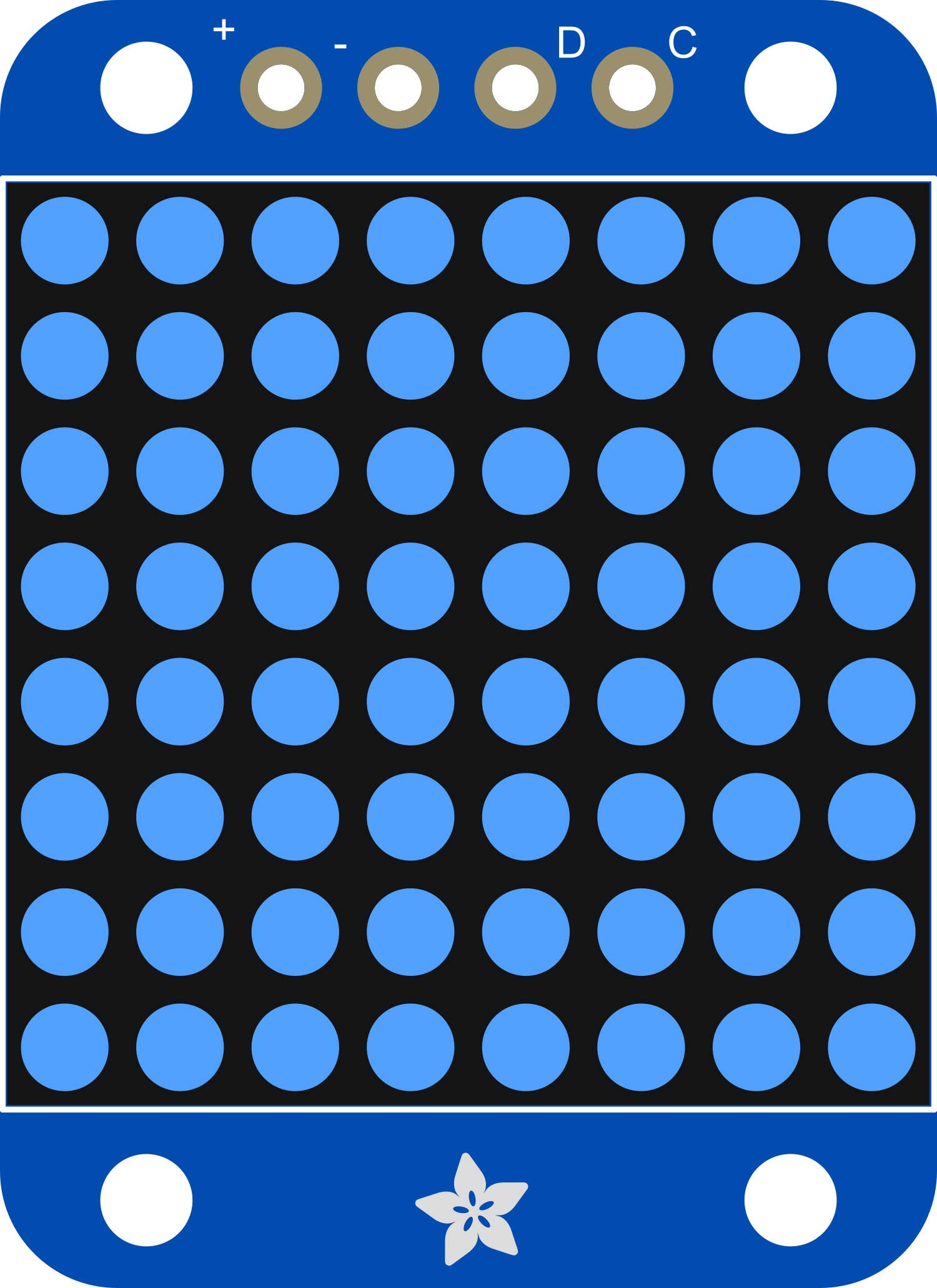
The Adafruit Mini 8x8 LED Matrix Backpack Blue is a compact and versatile electronic component designed to drive an 8x8 LED matrix with minimal effort and maximum efficiency. This backpack simplifies the process of controlling multiple LEDs by using an I2C interface, which reduces the number of pins required from the microcontroller. Common applications include creating small displays for showing characters, symbols, or custom graphics in projects such as wearables, digital signage, and gaming devices.
Explore Projects Built with Adafruit Mini 8x8 LED Matrix Backpack Blue
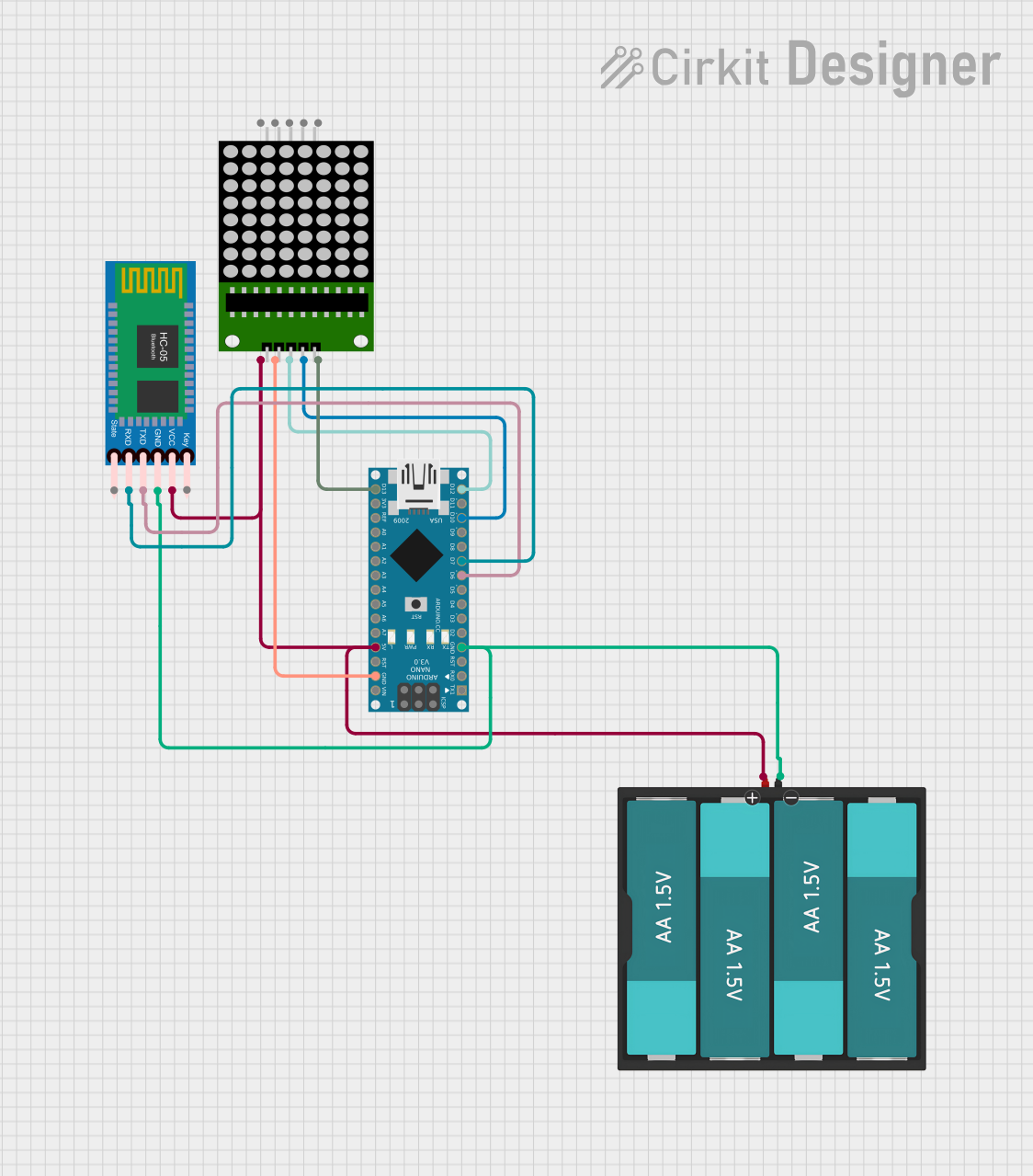


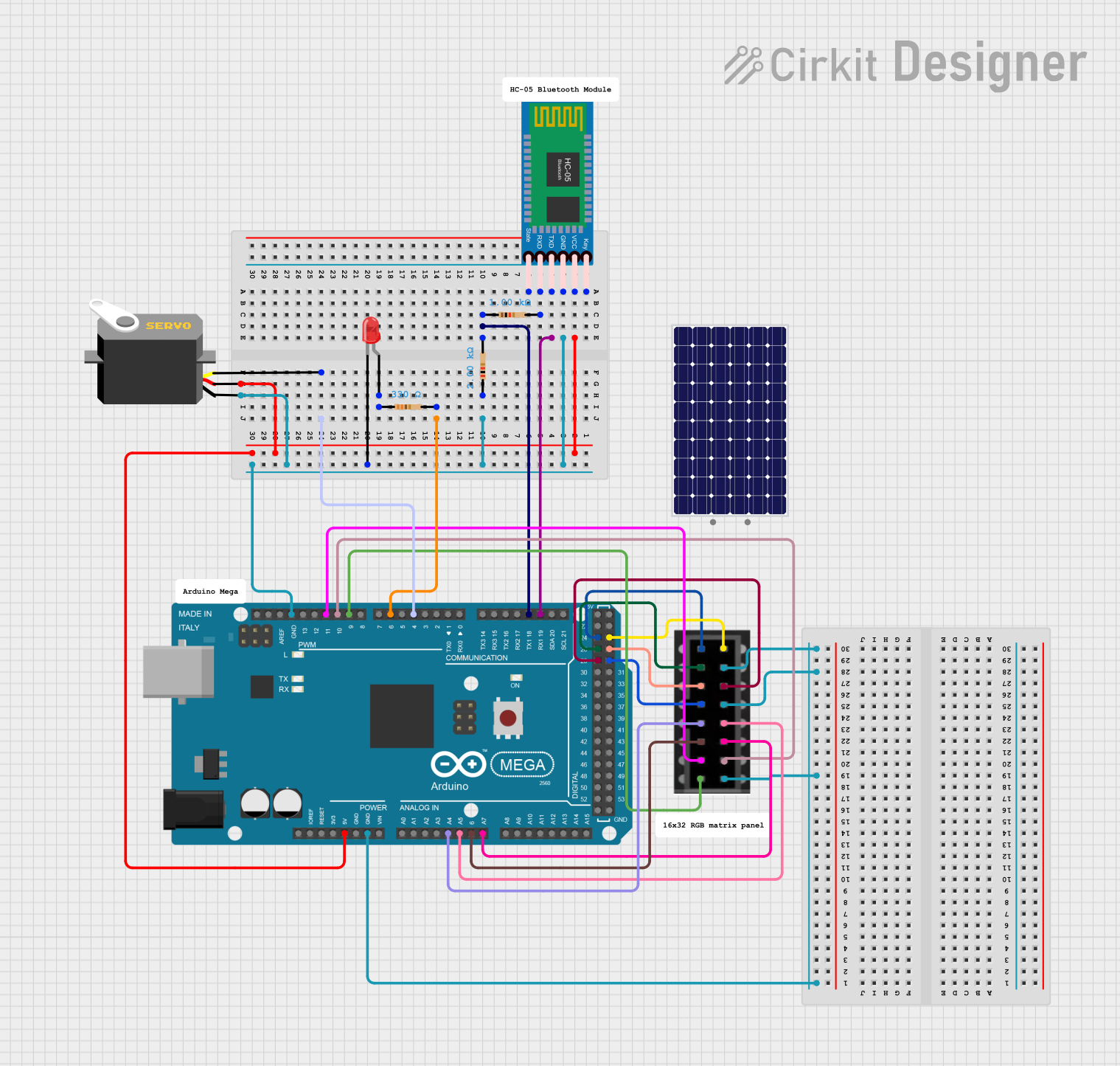
Explore Projects Built with Adafruit Mini 8x8 LED Matrix Backpack Blue
Technical Specifications
Key Technical Details
- Operating Voltage: 2.5V to 5.5V
- Max Current per LED: 30mA
- Max Current for all LEDs: 500mA
- Communication: I2C interface
- I2C Addresses: Selectable between 0x70-0x77
- Dimensions: 32mm x 32mm x 1.6mm / 1.3" x 1.3" x 0.06"
- Weight: 5g / 0.18oz
Pin Configuration and Descriptions
| Pin | Description |
|---|---|
| VCC | Power supply (2.5V to 5.5V) |
| GND | Ground |
| SDA | I2C Data |
| SCL | I2C Clock |
| ADDR | Address selection pin (connect to GND or VCC to set address) |
| RST | Reset pin (optional use) |
Usage Instructions
Connecting to an Arduino UNO
Power Connections:
- Connect the VCC pin to the 5V output on the Arduino.
- Connect the GND pin to one of the GND pins on the Arduino.
I2C Connections:
- Connect the SDA pin to the A4 pin (SDA) on the Arduino.
- Connect the SCL pin to the A5 pin (SCL) on the Arduino.
Address Selection:
- The ADDR pin can be left unconnected for the default address (0x70).
- Connect the ADDR pin to GND or VCC to set a different address if using multiple matrices.
Software Setup:
- Install the Adafruit LED Backpack library via the Arduino Library Manager.
- Include the library in your sketch.
Example Arduino Code
#include <Wire.h>
#include <Adafruit_GFX.h>
#include <Adafruit_LEDBackpack.h>

Adafruit_8x8matrix matrix = Adafruit_8x8matrix();

void setup() {
  matrix.begin(0x70); // Start the matrix using the I2C address
  matrix.setBrightness(10); // Set brightness to a value between 0 and 15
}

void loop() {
  matrix.clear(); // Clear the matrix display
  matrix.drawPixel(0, 0, LED_ON); // Turn on a single pixel (0,0)
  matrix.writeDisplay(); // Write the changes to the display
  delay(500);
  matrix.clear(); // Clear the display again
  matrix.writeDisplay(); // Write the changes to the display
  delay(500);
}
Important Considerations and Best Practices
- Ensure that the power supply voltage does not exceed 5.5V to prevent damage.
- When using multiple LED matrices, make sure to set unique I2C addresses for each.
- Avoid drawing too much current from the Arduino pins by not exceeding the maximum current ratings.
- Use a separate power supply when driving multiple matrices to provide sufficient current.
Troubleshooting and FAQs
Common Issues
- LEDs not lighting up: Check the power connections and ensure the I2C wires are properly connected to the correct Arduino pins.
- Garbled display: Ensure that the I2C address is correctly set and that there are no conflicts with other I2C devices.
- Dim display: Adjust the brightness using
setBrightness()function or check the power supply.
Solutions and Tips for Troubleshooting
- Double-check wiring connections for any loose or incorrect connections.
- Verify that the Adafruit LED Backpack library is correctly installed in the Arduino IDE.
- Use the
i2cdetectutility on Raspberry Pi or a similar scanner sketch on Arduino to confirm the device's I2C address. - Reset the Arduino and the LED matrix if the display behaves unexpectedly.
FAQs
Q: Can I use this LED matrix with a Raspberry Pi? A: Yes, the Adafruit Mini 8x8 LED Matrix Backpack can be used with a Raspberry Pi using the appropriate Python libraries.
Q: How do I control individual LEDs?
A: Individual LEDs can be controlled using the drawPixel() function, specifying the x and y coordinates and the state (ON or OFF).
Q: Can I display characters or shapes? A: Yes, the Adafruit GFX library provides functions to display characters, shapes, and even custom bitmaps.
Q: How many of these matrices can I chain together? A: You can chain up to 8 matrices together by setting unique I2C addresses for each one using the ADDR pin.