How to Use vibration sensor is a module: Examples, Pinouts, and Specs
Introduction
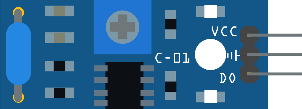
A vibration sensor module is a device designed to detect and measure the intensity of vibrations in its environment. It typically consists of a piezoelectric element or a spring-and-mass mechanism that generates an electrical signal in response to vibrations. These modules are widely used in applications such as security systems, industrial equipment monitoring, robotics, and home automation to detect movement, monitor machinery health, or identify anomalies.
Common use cases include:
- Detecting unauthorized access or tampering in security systems.
- Monitoring vibrations in industrial machines to predict maintenance needs.
- Measuring movement or impact in robotics and automation systems.
- Detecting earthquakes or structural vibrations in buildings.
Explore Projects Built with vibration sensor is a module
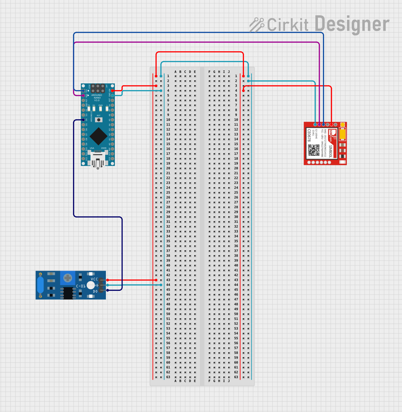
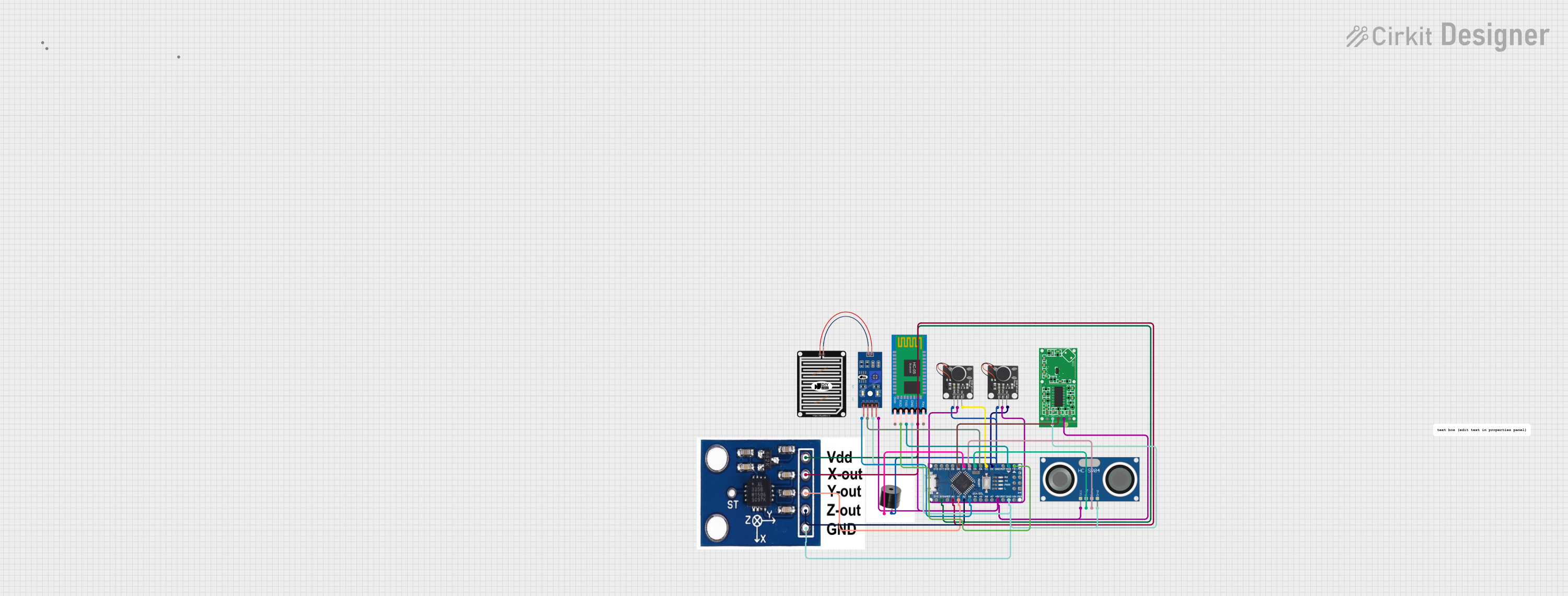


Explore Projects Built with vibration sensor is a module
Technical Specifications
Below are the key technical details of a typical vibration sensor module:
| Parameter | Value |
|---|---|
| Operating Voltage | 3.3V to 5V |
| Output Signal Type | Digital (High/Low) or Analog |
| Sensitivity Adjustment | Potentiometer (for some modules) |
| Output Current | 15mA (typical) |
| Dimensions | ~32mm x 14mm x 8mm |
| Operating Temperature | -20°C to 70°C |
Pin Configuration and Descriptions
The vibration sensor module typically has three pins:
| Pin | Name | Description |
|---|---|---|
| 1 | VCC | Connect to the positive power supply (3.3V to 5V). |
| 2 | GND | Connect to the ground of the power supply. |
| 3 | OUT | Output pin that provides a digital or analog signal based on the detected vibration. |
Usage Instructions
How to Use the Vibration Sensor Module in a Circuit
- Power the Module: Connect the
VCCpin to a 3.3V or 5V power supply and theGNDpin to the ground. - Connect the Output: Use the
OUTpin to read the sensor's output. This can be connected to a microcontroller (e.g., Arduino) or an external circuit.- For digital output: The pin will output a HIGH signal when vibration is detected and LOW otherwise.
- For analog output (if supported): The pin will output a voltage proportional to the vibration intensity.
- Adjust Sensitivity: If the module has a potentiometer, adjust it to set the desired sensitivity level.
Example Circuit with Arduino UNO
Below is an example of how to connect and use the vibration sensor module with an Arduino UNO:
Circuit Connections
- Connect the
VCCpin of the sensor to the 5V pin on the Arduino. - Connect the
GNDpin of the sensor to the GND pin on the Arduino. - Connect the
OUTpin of the sensor to digital pin 2 on the Arduino.
Arduino Code
// Vibration Sensor Module Example with Arduino UNO
// This code reads the digital output of the vibration sensor and
// turns on an LED when vibration is detected.

const int sensorPin = 2;  // Pin connected to the OUT pin of the sensor
const int ledPin = 13;    // Built-in LED pin on Arduino

void setup() {
  pinMode(sensorPin, INPUT);  // Set sensor pin as input
  pinMode(ledPin, OUTPUT);    // Set LED pin as output
  Serial.begin(9600);         // Initialize serial communication
}

void loop() {
  int sensorValue = digitalRead(sensorPin);  // Read the sensor output

  if (sensorValue == HIGH) {
    // Vibration detected
    digitalWrite(ledPin, HIGH);  // Turn on the LED
    Serial.println("Vibration detected!");
  } else {
    // No vibration
    digitalWrite(ledPin, LOW);   // Turn off the LED
  }

  delay(100);  // Small delay to stabilize readings
}
Important Considerations and Best Practices
- Power Supply: Ensure the module is powered within its operating voltage range (3.3V to 5V). Exceeding this range may damage the module.
- Sensitivity Adjustment: Use the onboard potentiometer (if available) to fine-tune the sensitivity based on your application.
- Mounting: Securely mount the sensor to avoid false readings caused by loose connections or external noise.
- Debouncing: If the sensor output fluctuates rapidly, consider implementing a software debounce mechanism to filter out noise.
Troubleshooting and FAQs
Common Issues and Solutions
No Output Signal
- Cause: Incorrect wiring or insufficient power supply.
- Solution: Double-check the connections and ensure the module is powered with the correct voltage.
False Triggers
- Cause: High sensitivity or external noise.
- Solution: Adjust the potentiometer to reduce sensitivity or shield the module from external vibrations.
Output Always HIGH or LOW
- Cause: Faulty sensor or incorrect sensitivity setting.
- Solution: Test the module with a known vibration source and adjust the sensitivity. Replace the module if it remains unresponsive.
Inconsistent Readings
- Cause: Loose connections or unstable power supply.
- Solution: Secure all connections and use a stable power source.
FAQs
Q1: Can the vibration sensor module detect small vibrations?
A1: Yes, the sensitivity can be adjusted using the onboard potentiometer (if available) to detect small vibrations.
Q2: Can I use this module with a 3.3V microcontroller?
A2: Yes, the module operates within a voltage range of 3.3V to 5V, making it compatible with 3.3V microcontrollers like ESP32 or Raspberry Pi Pico.
Q3: How do I know if the sensor is working?
A3: You can test the sensor by tapping it gently and observing the output signal (e.g., LED turning on or a HIGH signal on the microcontroller).
Q4: Can this module measure the intensity of vibrations?
A4: Some modules provide an analog output proportional to the vibration intensity. Check the module's specifications to confirm this feature.
By following this documentation, you can effectively integrate and troubleshoot a vibration sensor module in your projects.