How to Use R200 Chip UHF RFID Module: Examples, Pinouts, and Specs
Introduction
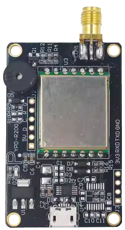
The R200 Chip UHF RFID Module (Manufacturer Part ID: YPD-R200) by Yanpodo is a compact and versatile RFID reader module designed for operation in the UHF frequency range (860–960 MHz). This module is capable of both reading and writing RFID tags, making it an essential component for a wide range of applications. Its small form factor and support for multiple communication interfaces make it easy to integrate into various systems.
Explore Projects Built with R200 Chip UHF RFID Module
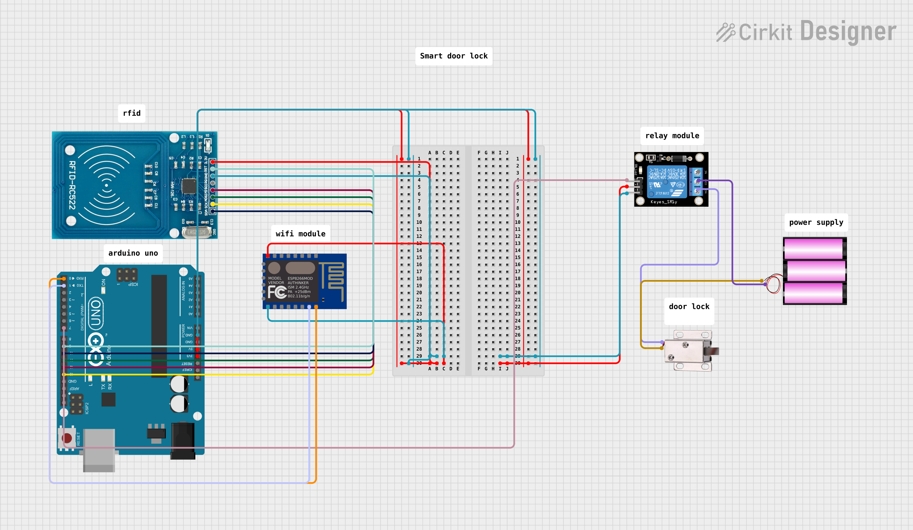
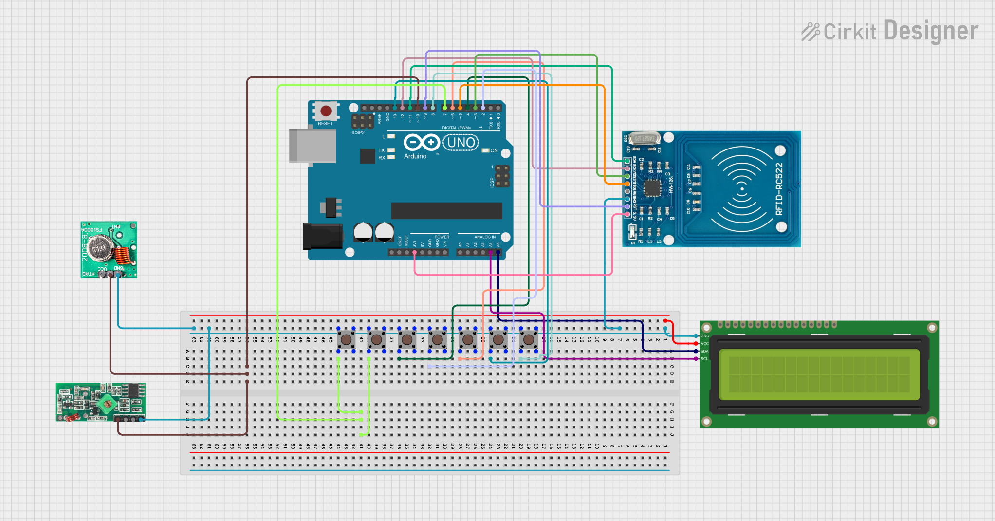

Explore Projects Built with R200 Chip UHF RFID Module
Common Applications
- Inventory Management: Automating stock tracking and reducing human error.
- Access Control: Managing secure entry points in buildings or restricted areas.
- Asset Tracking: Monitoring the location and status of valuable assets.
- Logistics and Supply Chain: Enhancing efficiency in package tracking and delivery.
- Retail: Enabling smart checkout systems and anti-theft solutions.
Technical Specifications
Key Technical Details
| Parameter | Specification |
|---|---|
| Operating Frequency | 860–960 MHz (UHF band) |
| Communication Interfaces | UART, I2C, SPI |
| Power Supply Voltage | 3.3V–5V DC |
| Current Consumption | 50 mA (typical), 100 mA (peak) |
| Reading Range | Up to 3 meters (depending on antenna) |
| Supported Protocols | EPCglobal Class 1 Gen 2 / ISO 18000-6C |
| Operating Temperature | -20°C to +70°C |
| Dimensions | 30 mm x 25 mm x 3 mm |
Pin Configuration and Descriptions
The R200 module has a 10-pin interface for power, communication, and control. Below is the pinout:
| Pin Number | Name | Description |
|---|---|---|
| 1 | VCC | Power supply input (3.3V–5V DC). |
| 2 | GND | Ground connection. |
| 3 | TXD | UART Transmit pin (for serial communication). |
| 4 | RXD | UART Receive pin (for serial communication). |
| 5 | SCL | I2C Clock line. |
| 6 | SDA | I2C Data line. |
| 7 | MOSI | SPI Master Out Slave In (data input to the module). |
| 8 | MISO | SPI Master In Slave Out (data output from the module). |
| 9 | SCK | SPI Clock line. |
| 10 | IRQ | Interrupt Request pin (used for signaling events like tag detection). |
Usage Instructions
How to Use the R200 Module in a Circuit
- Power Supply: Connect the VCC pin to a 3.3V–5V DC power source and the GND pin to ground.
- Communication Interface: Choose one of the supported communication interfaces (UART, I2C, or SPI) and connect the corresponding pins to your microcontroller or host device.
- For UART: Connect TXD and RXD to the respective UART pins on your microcontroller.
- For I2C: Connect SCL and SDA to the I2C clock and data lines.
- For SPI: Connect MOSI, MISO, and SCK to the SPI lines.
- Antenna: Attach a compatible UHF RFID antenna to the module to enable tag reading and writing.
- Initialization: Configure the module using the appropriate commands or library for your microcontroller.
Important Considerations and Best Practices
- Antenna Placement: Ensure the antenna is positioned away from metal objects to avoid interference.
- Power Supply: Use a stable power source to prevent voltage fluctuations that could affect performance.
- Communication Protocol: Match the communication protocol settings (e.g., baud rate for UART) between the module and your microcontroller.
- Tag Compatibility: Verify that the RFID tags conform to the supported protocols (EPCglobal Class 1 Gen 2 / ISO 18000-6C).
- Distance and Orientation: For optimal performance, ensure the RFID tags are within the specified reading range and properly oriented.
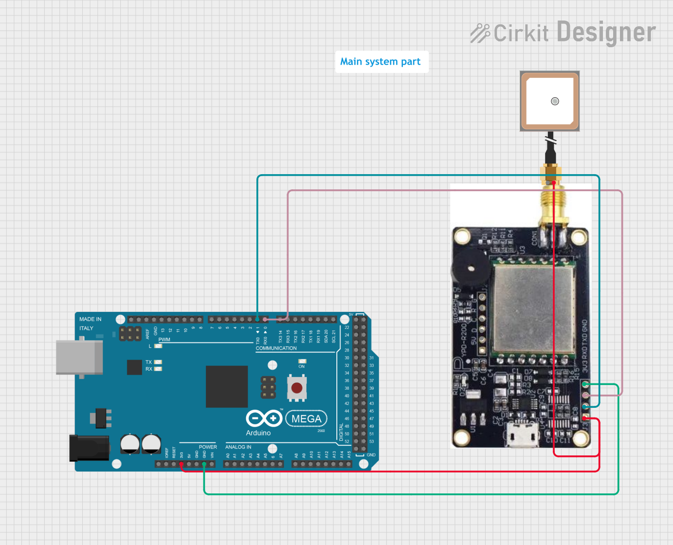
Example: Using the R200 Module with Arduino UNO (UART Interface)
Below is an example of how to connect and use the R200 module with an Arduino UNO via UART:
Wiring
| R200 Pin | Arduino Pin |
|---|---|
| VCC | 5V |
| GND | GND |
| TXD | RX (Pin 0) |
| RXD | TX (Pin 1) |
Code
#include <SoftwareSerial.h>

// Define RX and TX pins for SoftwareSerial
SoftwareSerial rfidSerial(10, 11); // RX = Pin 10, TX = Pin 11

void setup() {
  Serial.begin(9600); // Initialize Serial Monitor
  rfidSerial.begin(9600); // Initialize RFID module communication

  Serial.println("R200 RFID Module Initialized");
}

void loop() {
  // Check if data is available from the RFID module
  if (rfidSerial.available()) {
    String tagData = "";

    // Read data from the module
    while (rfidSerial.available()) {
      char c = rfidSerial.read();
      tagData += c;
    }

    // Print the tag data to the Serial Monitor
    Serial.print("Tag Detected: ");
    Serial.println(tagData);
  }
}
Notes:
- Use a level shifter if your Arduino operates at 5V logic levels to avoid damaging the module.
- Ensure the RFID antenna is connected before powering on the module.
Troubleshooting and FAQs
Common Issues and Solutions
Module Not Responding
- Cause: Incorrect wiring or power supply issues.
- Solution: Double-check all connections and ensure the power supply voltage is within the specified range (3.3V–5V).
Poor Reading Range
- Cause: Interference from nearby metal objects or improper antenna placement.
- Solution: Reposition the antenna and ensure it is not obstructed by metal objects.
No Data from Module
- Cause: Mismatched communication settings (e.g., baud rate).
- Solution: Verify that the communication settings on the microcontroller match the module's default settings.
Intermittent Operation
- Cause: Unstable power supply or loose connections.
- Solution: Use a regulated power supply and secure all connections.
FAQs
Q: Can the R200 module read multiple tags simultaneously?
A: Yes, the module supports anti-collision protocols, allowing it to read multiple tags within range.Q: What is the default baud rate for UART communication?
A: The default baud rate is 9600 bps.Q: Can I use the R200 module outdoors?
A: Yes, but ensure it is housed in a weatherproof enclosure to protect it from environmental factors.Q: Is the module compatible with 5V logic microcontrollers?
A: Yes, the module supports 3.3V–5V logic levels, making it compatible with most microcontrollers.
This concludes the documentation for the R200 Chip UHF RFID Module. For further assistance, refer to the manufacturer's datasheet or contact Yanpodo support.