
Ceramic Capacitor

Ceramic Capacitor Documentation
Introduction
A ceramic capacitor is a passive electronic component that stores electrical energy in an electric field. It is constructed using two or more alternating layers of ceramic material and metal conductors. The ceramic material acts as the dielectric. Ceramic capacitors are widely used due to their small size, high reliability, and low cost. They are commonly found in applications such as filtering, bypassing, and coupling in a wide range of electronic circuits, including high-frequency and low-impedance applications such as RF circuits.
Technical Specifications
Key Technical Details
- Dielectric Type: Ceramic
- Capacitance Range: Typically from picofarads (pF) to microfarads (µF)
- Voltage Ratings: From a few volts to several kilovolts, depending on the type
- Tolerance: Varies, common values include ±5%, ±10%, and ±20%
- Temperature Coefficient: Classified by codes such as NP0, X7R, Y5V, etc.
- Operating Temperature Range: Usually from -55°C to +125°C
Pin Configuration and Descriptions
Ceramic capacitors are typically non-polarized and do not have a pin configuration. They have two terminals that can be connected to a circuit in any orientation.
| Terminal | Description |
|---|---|
| 1 | Terminal 1 (can be connected to either polarity) |
| 2 | Terminal 2 (can be connected to either polarity) |
Usage Instructions
How to Use in a Circuit
- Identify Capacitance and Voltage Rating: Select a ceramic capacitor with the appropriate capacitance and voltage rating for your application.
- Circuit Placement: Connect the capacitor in parallel with the signal or power line where filtering or decoupling is needed.
- Orientation: Since ceramic capacitors are non-polarized, they can be installed in either direction.
- Soldering: Use appropriate soldering techniques to attach the capacitor to the PCB, avoiding excessive heat that could damage the component.
Important Considerations and Best Practices
- Voltage Rating: Always choose a capacitor with a voltage rating higher than the maximum voltage expected in the circuit.
- Temperature Coefficient: Select a dielectric material suitable for the operating temperature range and stability requirements.
- Physical Size: Ensure the physical size of the capacitor is suitable for the layout and spacing of the PCB.
- Handling: Ceramic capacitors can be brittle. Handle them with care to avoid physical damage.
Troubleshooting and FAQs
Common Issues
- Capacitor Failure: Overvoltage, physical damage, or excessive temperature can cause failure.
- Noise Issues: Incorrect capacitor value or type can result in inadequate filtering or noise suppression.
Solutions and Tips
- Overvoltage: Replace the capacitor with one that has a higher voltage rating.
- Physical Damage: Handle capacitors carefully during installation and use. Inspect for cracks or damage before use.
- Noise Suppression: If noise issues persist, consider using a capacitor with a different dielectric material or a different capacitance value.
FAQs
Q: Can I replace a ceramic capacitor with one of a different capacitance? A: It depends on the circuit. For filtering applications, the capacitance value is often critical. For decoupling applications, there is more flexibility, but the replacement should be within the same order of magnitude.
Q: What does the temperature coefficient code on a ceramic capacitor mean? A: The temperature coefficient code indicates how the capacitance value changes over temperature. NP0 (C0G) has the least change, while Y5V has the most.
Q: How do I know if a ceramic capacitor is damaged? A: Physical inspection can reveal cracks or damage. Electrically, a damaged capacitor may show a short circuit, open circuit, or significant change in capacitance.
Q: Can ceramic capacitors be used for AC applications? A: Yes, ceramic capacitors can be used in AC applications, but ensure the AC voltage does not exceed the capacitor's voltage rating.
Example Code for Arduino UNO
If you're using a ceramic capacitor in conjunction with an Arduino UNO for debounce in a button circuit, here's a simple example code:
// Define the button pin
const int buttonPin = 2;
// Define the LED pin
const int ledPin = 13;
// Variable for the button state
int buttonState = 0;

void setup() {
  // Initialize the LED pin as an output
  pinMode(ledPin, OUTPUT);
  // Initialize the button pin as an input
  pinMode(buttonPin, INPUT);
}

void loop() {
  // Read the state of the button
  buttonState = digitalRead(buttonPin);
  // Check if the button is pressed.
  // If it is, the buttonState is HIGH:
  if (buttonState == HIGH) {
    // Turn on the LED
    digitalWrite(ledPin, HIGH);
  } else {
    // Turn off the LED
    digitalWrite(ledPin, LOW);
  }
}
In this code, the ceramic capacitor would be connected across the button terminals to debounce the signal, ensuring stable HIGH or LOW readings.
Example Projects
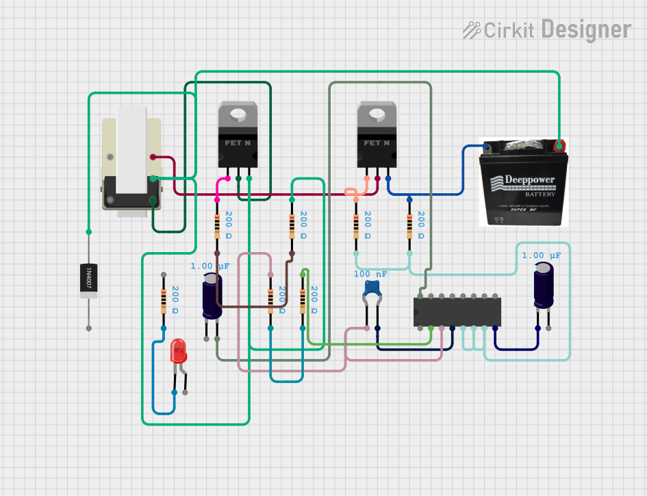
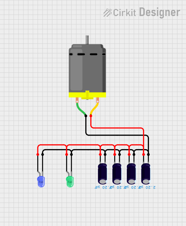
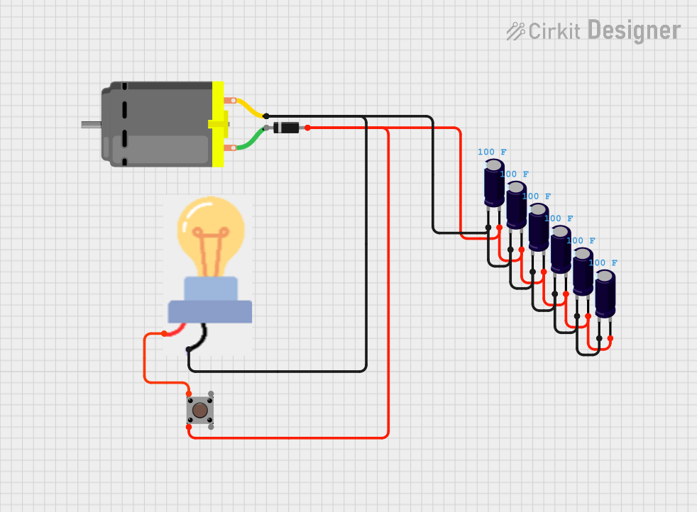
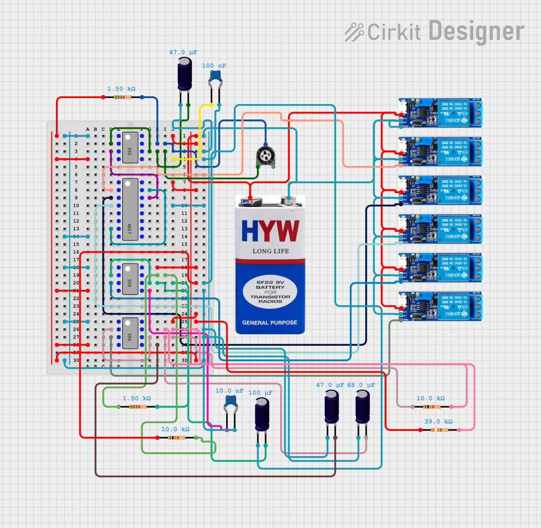
Example Projects


