How to Use pinlab iot 3: Examples, Pinouts, and Specs
Introduction
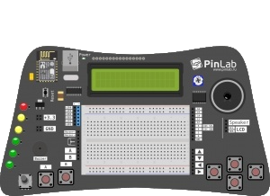
The PinLab IoT 3 is a versatile development board designed for Internet of Things (IoT) applications. Manufactured by PinLab with the part ID MAXI, this board is equipped with multiple connectivity options, onboard sensors, and a user-friendly interface. It is ideal for prototyping and testing IoT solutions, making it a valuable tool for hobbyists, students, and professionals alike.
Explore Projects Built with pinlab iot 3
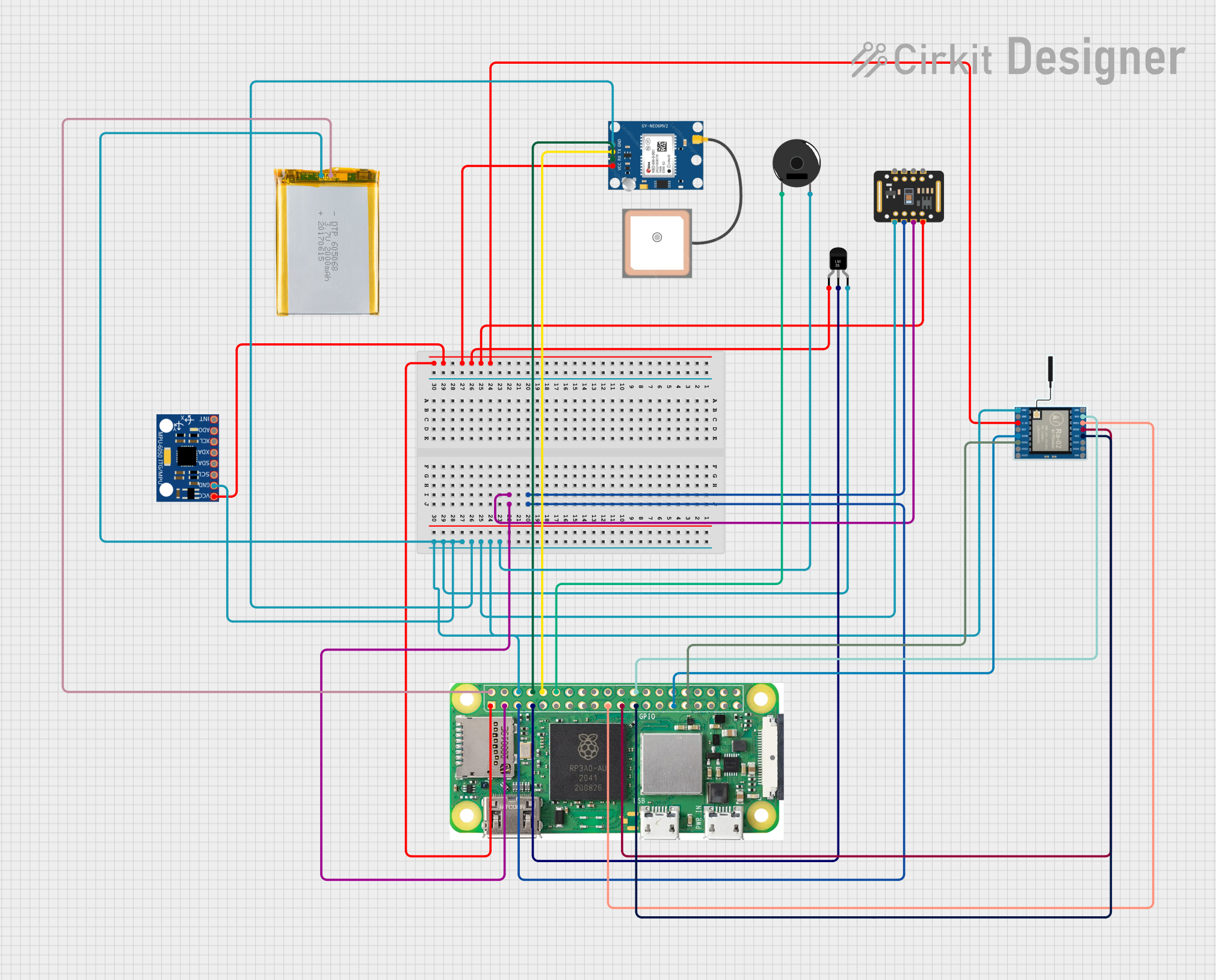
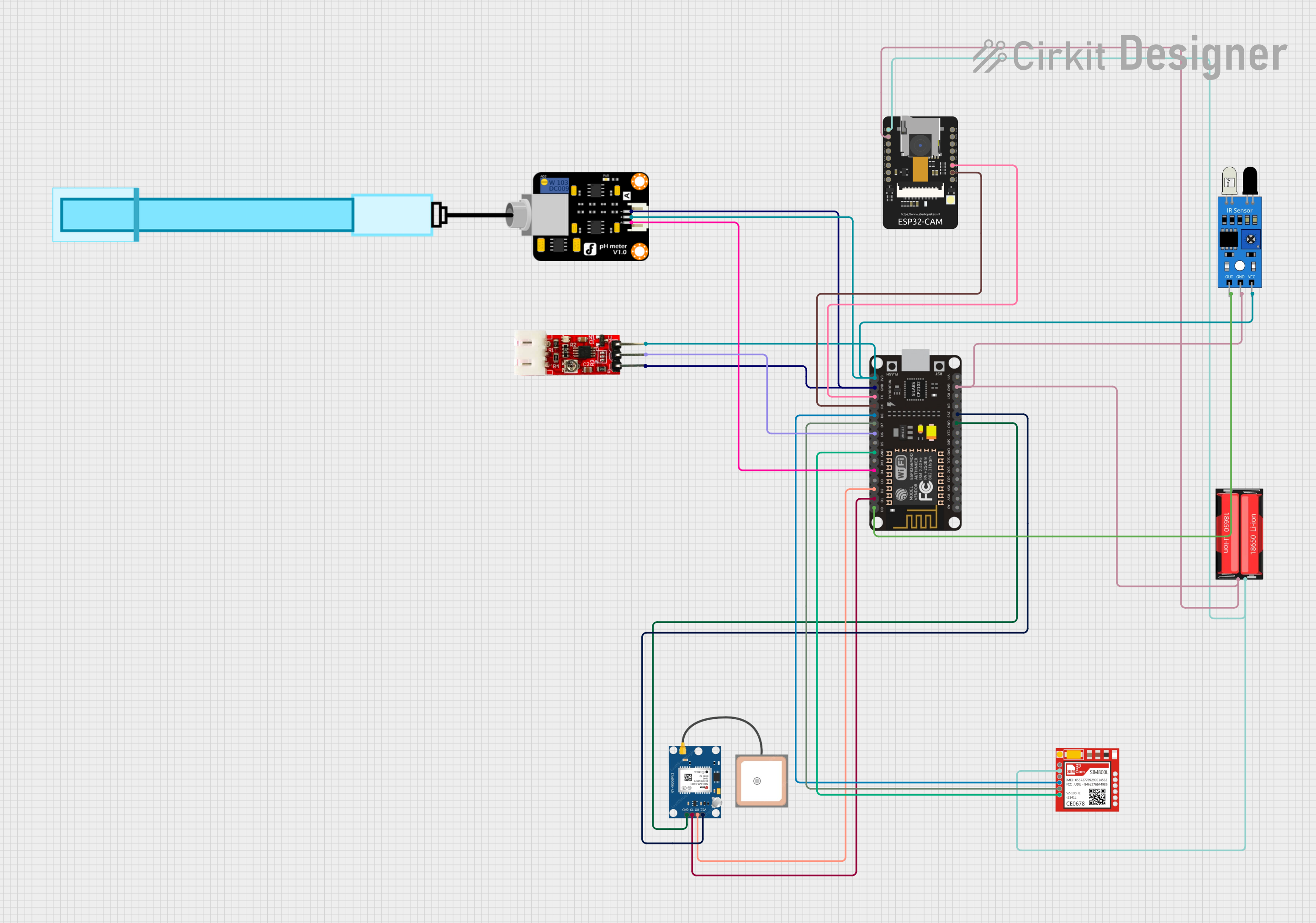
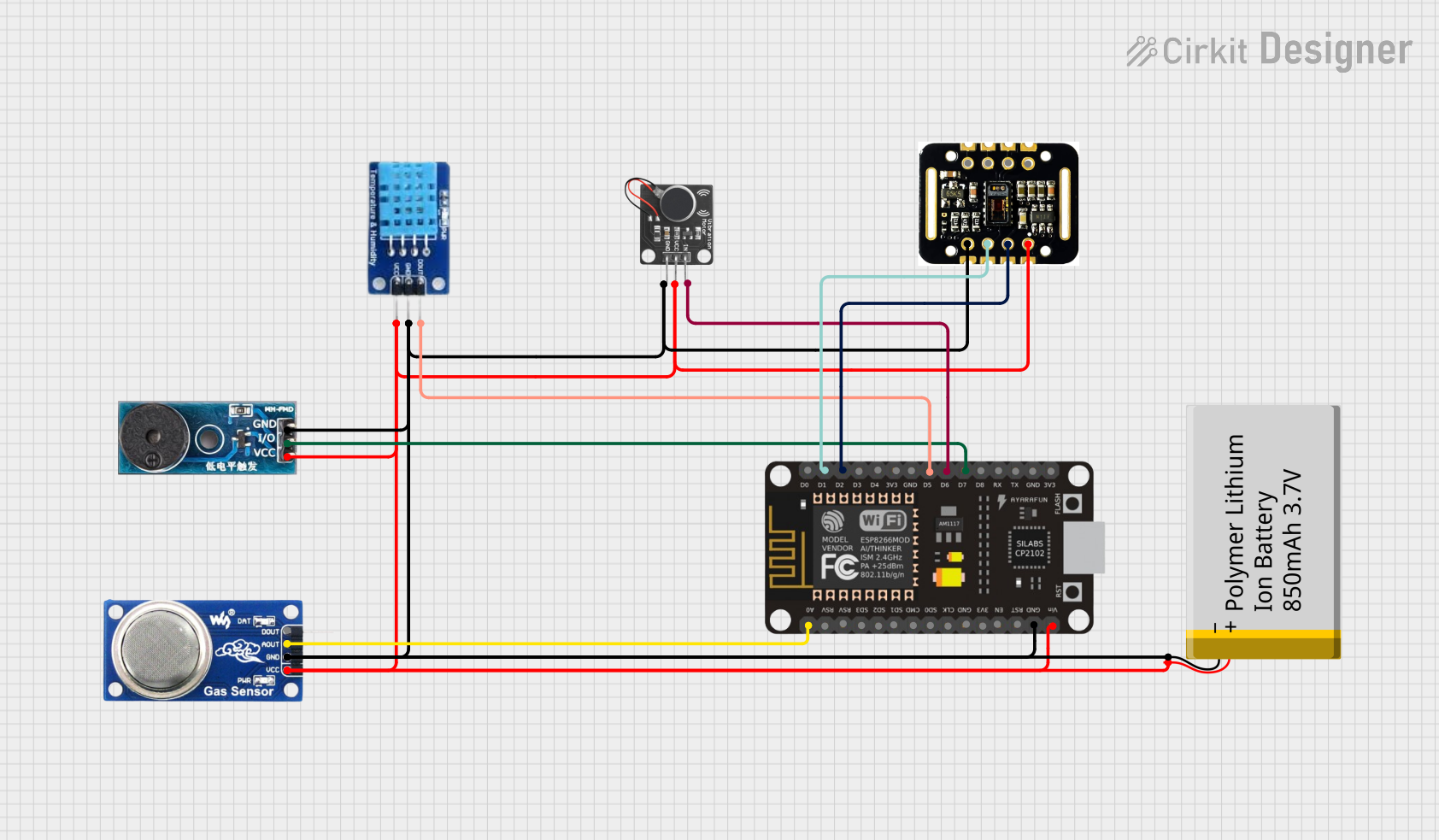
Explore Projects Built with pinlab iot 3
Common Applications and Use Cases
- Smart home automation systems
- Environmental monitoring and data logging
- Industrial IoT applications
- Wearable technology prototyping
- Educational projects and IoT workshops
Technical Specifications
Key Technical Details
| Specification | Value |
|---|---|
| Microcontroller | ARM Cortex-M4 |
| Operating Voltage | 3.3V |
| Input Voltage Range | 5V (via USB) or 7-12V (via VIN pin) |
| Connectivity Options | Wi-Fi (802.11 b/g/n), Bluetooth 5.0 |
| Onboard Sensors | Temperature, Humidity, Light, Accelerometer |
| GPIO Pins | 20 (Digital: 14, Analog: 6) |
| Communication Protocols | UART, SPI, I2C |
| Flash Memory | 1MB |
| SRAM | 256KB |
| Dimensions | 60mm x 30mm |
Pin Configuration and Descriptions
| Pin Number | Pin Name | Description |
|---|---|---|
| 1 | VIN | Input voltage (7-12V) |
| 2 | GND | Ground |
| 3 | 3.3V | Regulated 3.3V output |
| 4 | D0-D13 | Digital I/O pins |
| 5 | A0-A5 | Analog input pins |
| 6 | TX, RX | UART communication pins |
| 7 | SDA, SCL | I2C communication pins |
| 8 | SPI Pins | MOSI, MISO, SCK, SS |
| 9 | RST | Reset pin |
Usage Instructions
How to Use the Component in a Circuit
Powering the Board:
- Connect the board to a USB power source (5V) or use the VIN pin for external power (7-12V).
- Ensure the power supply is stable to avoid damaging the board.
Connecting Sensors and Actuators:
- Use the GPIO pins (D0-D13) for digital sensors or actuators.
- For analog sensors, connect to the analog input pins (A0-A5).
Programming the Board:
- The PinLab IoT 3 is compatible with the Arduino IDE. Install the necessary board definitions from the PinLab repository.
- Connect the board to your computer via USB and select the correct COM port in the Arduino IDE.
Using Connectivity Features:
- For Wi-Fi, use the onboard library to connect to a network and send/receive data.
- For Bluetooth, pair the board with a compatible device and use the UART interface for communication.
Important Considerations and Best Practices
- Avoid exceeding the voltage and current ratings of the pins to prevent damage.
- Use pull-up or pull-down resistors for GPIO pins when necessary.
- Ensure proper grounding when connecting external components.
- Update the firmware regularly to access the latest features and bug fixes.
Example Code for Arduino UNO
Below is an example code snippet to read the onboard temperature sensor and send the data over Wi-Fi:
#include <WiFi.h> // Include Wi-Fi library for connectivity

// Wi-Fi credentials
const char* ssid = "Your_SSID";
const char* password = "Your_PASSWORD";

// Pin for temperature sensor
const int tempSensorPin = A0;

void setup() {
  Serial.begin(9600); // Initialize serial communication
  WiFi.begin(ssid, password); // Connect to Wi-Fi

  // Wait for Wi-Fi connection
  while (WiFi.status() != WL_CONNECTED) {
    delay(1000);
    Serial.println("Connecting to Wi-Fi...");
  }
  Serial.println("Connected to Wi-Fi!");
}

void loop() {
  // Read temperature sensor value
  int sensorValue = analogRead(tempSensorPin);

  // Convert sensor value to temperature (example conversion)
  float temperature = (sensorValue / 1024.0) * 100.0;

  // Print temperature to Serial Monitor
  Serial.print("Temperature: ");
  Serial.print(temperature);
  Serial.println(" °C");

  delay(2000); // Wait 2 seconds before next reading
}
Troubleshooting and FAQs
Common Issues and Solutions
Board Not Detected by Computer:
- Ensure the USB cable is functional and properly connected.
- Install the correct drivers for the PinLab IoT 3 board.
Wi-Fi Connection Fails:
- Double-check the SSID and password.
- Ensure the Wi-Fi network is within range and operational.
Incorrect Sensor Readings:
- Verify the sensor connections and ensure proper grounding.
- Calibrate the sensors if necessary.
Overheating:
- Check for short circuits or excessive current draw.
- Use a heat sink if the board operates in high-temperature environments.
FAQs
Q: Can I use the PinLab IoT 3 with other IDEs besides Arduino?
A: Yes, the board is compatible with other IDEs like PlatformIO, provided you install the appropriate libraries and configurations.
Q: What is the maximum range for Bluetooth connectivity?
A: The Bluetooth 5.0 module has a typical range of up to 10 meters indoors and 50 meters outdoors, depending on environmental factors.
Q: Can I power the board using a battery?
A: Yes, you can use a 7-12V battery connected to the VIN pin or a 3.7V LiPo battery with a suitable voltage regulator.
Q: Is the board compatible with IoT cloud platforms?
A: Absolutely! The PinLab IoT 3 supports integration with popular IoT platforms like AWS IoT, Google Cloud IoT, and ThingSpeak.