
How to Use STC-1000: Examples, Pinouts, and Specs
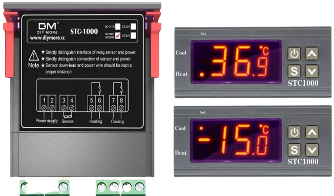
 Design with STC-1000 in Cirkit Designer
Introduction
The STC-1000 is a versatile digital temperature controller manufactured by BOE (Part ID: BOE). It is widely used for regulating temperature in a variety of applications, including incubators, refrigerators, aquariums, and fermentation chambers. The device features a dual relay output for controlling both heating and cooling systems, a digital temperature display, and user-adjustable set points for precise temperature management. Its compact design and ease of use make it a popular choice for both hobbyists and professionals.
Explore Projects Built with STC-1000
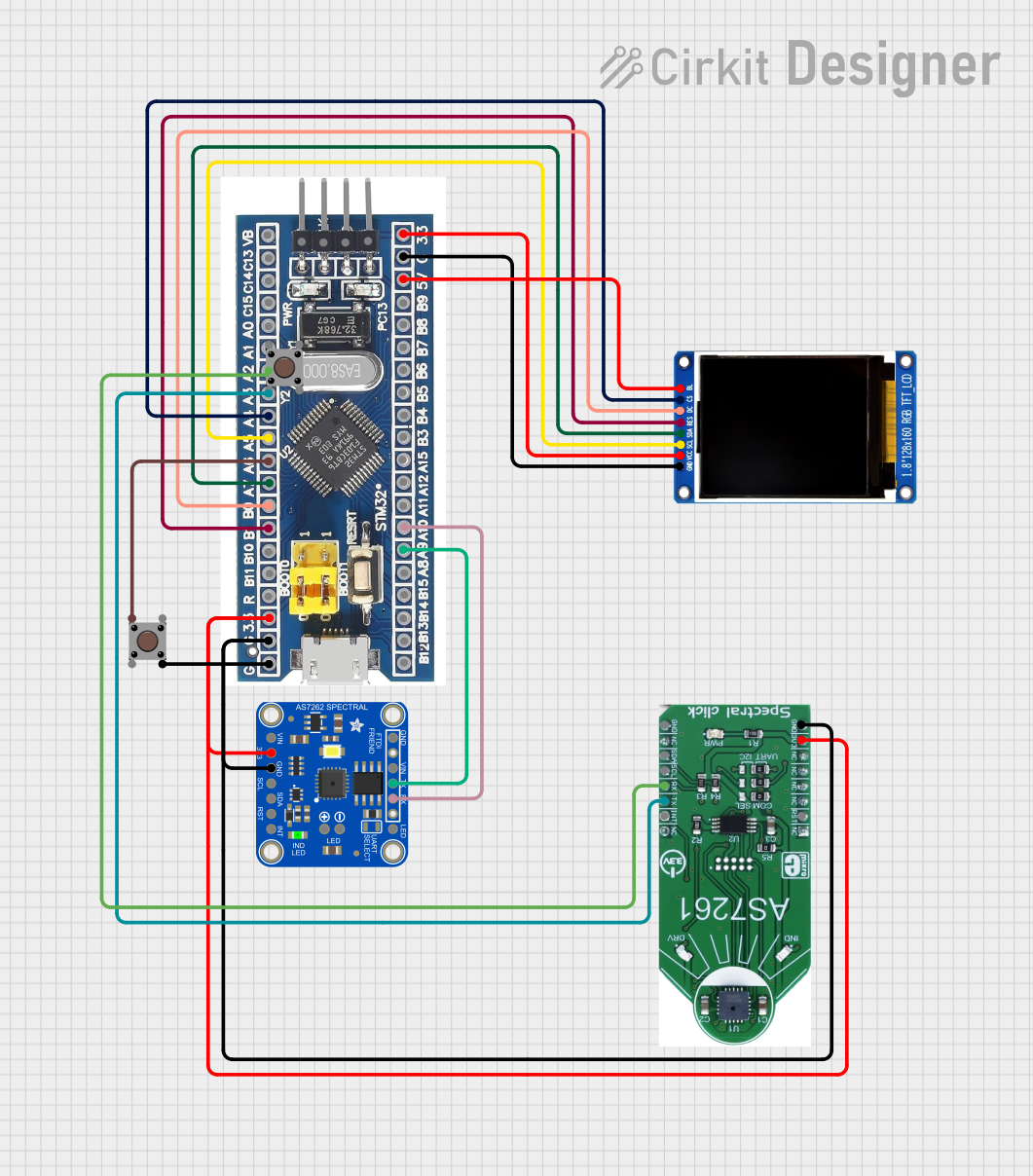 Open Project in Cirkit Designer
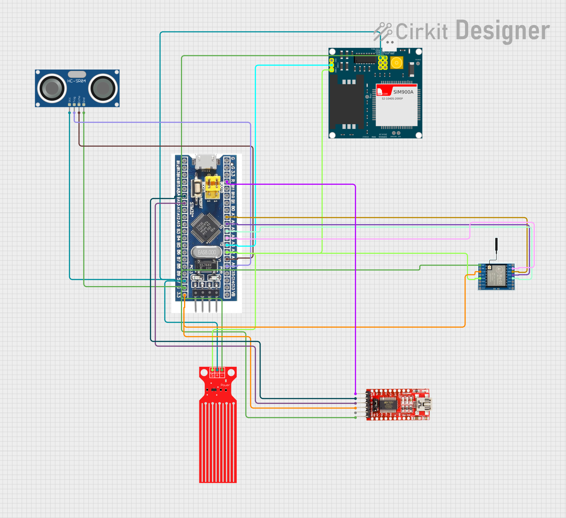 Open Project in Cirkit Designer
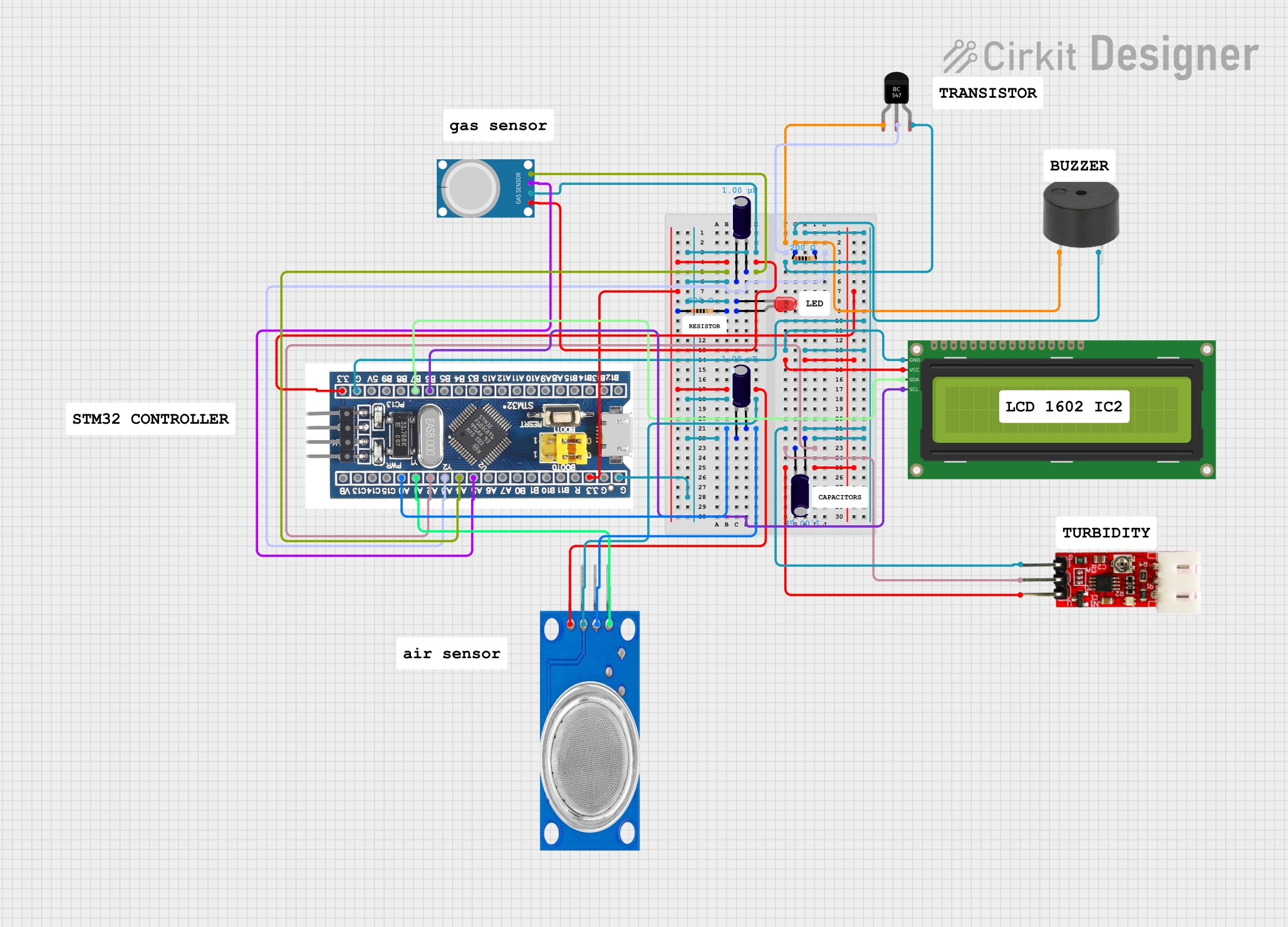 Open Project in Cirkit Designer
 Open Project in Cirkit Designer
Explore Projects Built with STC-1000
Open Project in Cirkit DesignerOpen Project in Cirkit DesignerOpen Project in Cirkit DesignerOpen Project in Cirkit DesignerCommon Applications
- Temperature regulation in homebrewing and fermentation processes
- Maintaining stable temperatures in aquariums and terrariums
- Controlling heating and cooling systems in incubators
- General-purpose temperature control in refrigerators and freezers
Technical Specifications
The following table outlines the key technical specifications of the STC-1000:
| Parameter | Specification |
|---|---|
| Operating Voltage | AC 110V-220V ±10% |
| Temperature Range | -50°C to 99°C (-58°F to 210°F) |
| Temperature Accuracy | ±1°C |
| Sensor Type | NTC (10kΩ) Thermistor |
| Relay Output (Heating) | 10A at 220V AC |
| Relay Output (Cooling) | 10A at 220V AC |
| Power Consumption | ≤3W |
| Display Type | LED (3-digit) |
| Operating Temperature | -10°C to 60°C |
| Storage Temperature | -20°C to 75°C |
| Dimensions | 75mm x 34.5mm x 85mm |
Pin Configuration and Descriptions
The STC-1000 has a total of 8 terminals for wiring. The table below describes each terminal:
| Terminal Number | Description |
|---|---|
| 1 | Power Input (Live/Hot wire) |
| 2 | Power Input (Neutral wire) |
| 3 | Cooling Relay Output (Live/Hot wire) |
| 4 | Cooling Relay Output (Neutral wire) |
| 5 | Heating Relay Output (Live/Hot wire) |
| 6 | Heating Relay Output (Neutral wire) |
| 7 | Temperature Sensor Input (NTC Thermistor) |
| 8 | Temperature Sensor Input (NTC Thermistor) |
Usage Instructions
How to Use the STC-1000 in a Circuit
- Wiring the Power Supply: Connect terminals 1 and 2 to the AC power supply (110V-220V). Ensure proper polarity and secure connections.
- Connecting the Temperature Sensor: Attach the NTC thermistor to terminals 7 and 8. Place the sensor in the environment where temperature regulation is required.
- Wiring the Heating and Cooling Devices:
- Connect the heating device to terminals 5 and 6.
- Connect the cooling device to terminals 3 and 4.
- Setting the Temperature:
- Power on the STC-1000.
- Use the "Set" button to adjust the desired temperature set point.
- Configure the heating and cooling differential values as needed.
Important Considerations
- Ensure that the connected heating and cooling devices do not exceed the relay's maximum current rating (10A at 220V AC).
- Place the temperature sensor in a location that accurately reflects the environment's temperature.
- Avoid exposing the STC-1000 to moisture or extreme temperatures beyond its operating range.
- Use proper insulation and secure all connections to prevent electrical hazards.
Example: Using the STC-1000 with an Arduino UNO
While the STC-1000 is a standalone device, it can be integrated with an Arduino UNO for advanced monitoring or automation. Below is an example Arduino sketch to read the temperature from the STC-1000's NTC sensor:
// Example code to read temperature from an NTC thermistor connected to Arduino
// Note: This assumes the NTC thermistor is connected to an analog pin (e.g., A0).

const int sensorPin = A0;  // Analog pin connected to the NTC thermistor
const float seriesResistor = 10000.0;  // Resistor value in series with the thermistor
const float nominalResistance = 10000.0;  // Resistance of the thermistor at 25°C
const float nominalTemperature = 25.0;  // Nominal temperature in Celsius
const float betaCoefficient = 3950.0;  // Beta coefficient of the thermistor

void setup() {
  Serial.begin(9600);  // Initialize serial communication
}

void loop() {
  int analogValue = analogRead(sensorPin);  // Read the analog value
  float voltage = analogValue * (5.0 / 1023.0);  // Convert to voltage
  float resistance = (5.0 - voltage) * seriesResistor / voltage;  // Calculate resistance

  // Calculate temperature using the Steinhart-Hart equation
  float steinhart;
  steinhart = resistance / nominalResistance;  // (R/Ro)
  steinhart = log(steinhart);  // ln(R/Ro)
  steinhart /= betaCoefficient;  // 1/B * ln(R/Ro)
  steinhart += 1.0 / (nominalTemperature + 273.15);  // + (1/To)
  steinhart = 1.0 / steinhart;  // Invert
  steinhart -= 273.15;  // Convert to Celsius

  Serial.print("Temperature: ");
  Serial.print(steinhart);
  Serial.println(" °C");

  delay(1000);  // Wait 1 second before the next reading
}
Troubleshooting and FAQs
Common Issues
No Power to the STC-1000:
- Check the power supply connections to terminals 1 and 2.
- Verify that the input voltage is within the specified range (110V-220V).
Temperature Reading is Inaccurate:
- Ensure the NTC thermistor is properly connected to terminals 7 and 8.
- Verify that the sensor is placed in an appropriate location for accurate readings.
Heating or Cooling Device Not Activating:
- Check the wiring of the heating and cooling devices to their respective terminals.
- Ensure the devices do not exceed the relay's current rating (10A at 220V AC).
- Verify that the temperature set points and differential values are correctly configured.
Display Shows Error Codes:
- E1: Sensor error. Check the connection of the NTC thermistor.
- EE: Memory error. Reset the device or reconfigure the settings.
Tips for Troubleshooting
- Use a multimeter to verify voltage and continuity in the circuit.
- Double-check all connections for loose wires or incorrect polarity.
- Refer to the user manual for additional error codes and troubleshooting steps.
By following this documentation, users can effectively utilize the STC-1000 for precise temperature control in various applications.