
How to Use YL-99 Limit switch and LED: Examples, Pinouts, and Specs
 Design with YL-99 Limit switch and LED in Cirkit Designer
Introduction
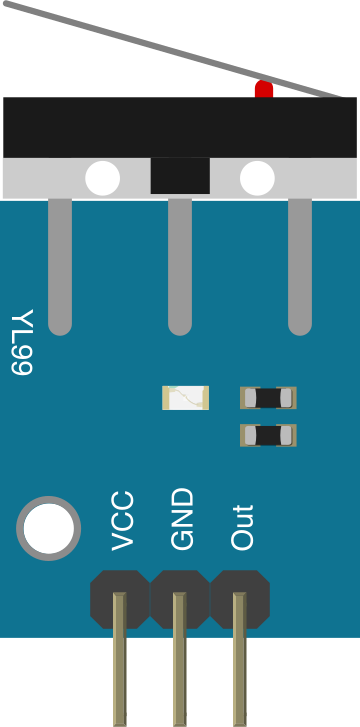
The YL-99 is a compact and versatile limit switch module that integrates a mechanical switch and an onboard LED indicator. It is commonly used in projects requiring position detection, end-stop detection, or mechanical event triggering. The module is designed for ease of use with microcontrollers like Arduino, Raspberry Pi, and other development boards.
The onboard LED provides a visual indication of the switch's state, making it ideal for debugging and monitoring. Its small size and simple interface make it suitable for robotics, CNC machines, 3D printers, and other automation systems.
Explore Projects Built with YL-99 Limit switch and LED
 Open Project in Cirkit Designer
 Open Project in Cirkit Designer
 Open Project in Cirkit Designer
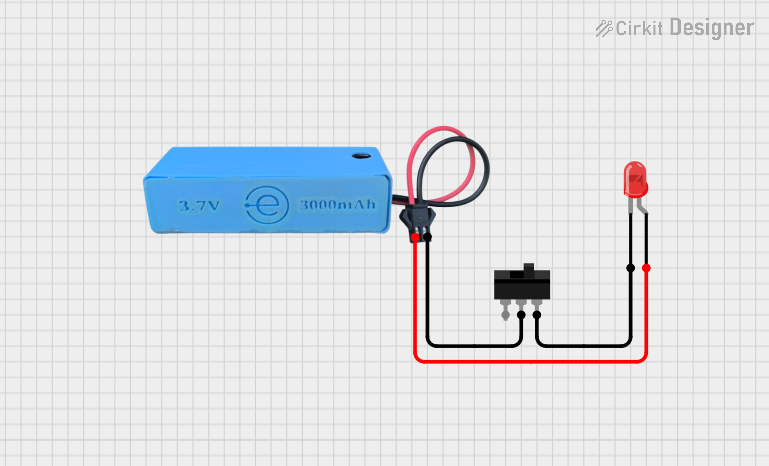 Open Project in Cirkit Designer
Explore Projects Built with YL-99 Limit switch and LED
Open Project in Cirkit DesignerOpen Project in Cirkit DesignerOpen Project in Cirkit DesignerOpen Project in Cirkit DesignerTechnical Specifications
- Operating Voltage: 3.3V to 5V DC
- Switch Type: Mechanical momentary switch
- Output Type: Digital (HIGH/LOW)
- Indicator: Onboard LED (lights up when the switch is pressed)
- Dimensions: 32mm x 10mm x 10mm (approx.)
- Mounting Holes: 2 holes for secure attachment
Pin Configuration and Descriptions
The YL-99 module has a 3-pin interface. Below is the pin configuration:
| Pin Name | Description |
|---|---|
| VCC | Power supply input (3.3V to 5V DC) |
| GND | Ground connection |
| OUT | Digital output signal (HIGH/LOW) |
Usage Instructions
How to Use the YL-99 in a Circuit
Wiring the Module:
- Connect the
VCCpin to the 3.3V or 5V pin of your microcontroller. - Connect the
GNDpin to the ground (GND) of your microcontroller. - Connect the
OUTpin to a digital input pin on your microcontroller.
- Connect the
Operation:
- When the switch is not pressed, the
OUTpin outputs a HIGH signal. - When the switch is pressed, the
OUTpin outputs a LOW signal, and the onboard LED lights up.
- When the switch is not pressed, the
Example Circuit:
- Use a pull-up resistor if necessary to ensure stable signal levels.
- The onboard LED provides a visual cue, but you can also monitor the
OUTpin in your microcontroller code.
Arduino UNO Example Code
Below is an example code snippet to use the YL-99 module with an Arduino UNO:
// Define the pin connected to the YL-99 OUT pin
const int limitSwitchPin = 2; // Digital pin 2
const int ledPin = 13;        // Built-in LED on Arduino UNO

void setup() {
  pinMode(limitSwitchPin, INPUT); // Set the limit switch pin as input
  pinMode(ledPin, OUTPUT);        // Set the built-in LED pin as output
  Serial.begin(9600);             // Initialize serial communication
}

void loop() {
  int switchState = digitalRead(limitSwitchPin); // Read the state of the switch

  if (switchState == LOW) {
    // If the switch is pressed
    digitalWrite(ledPin, HIGH); // Turn on the built-in LED
    Serial.println("Switch Pressed!");
  } else {
    // If the switch is not pressed
    digitalWrite(ledPin, LOW);  // Turn off the built-in LED
    Serial.println("Switch Released!");
  }

  delay(100); // Small delay for stability
}
Important Considerations and Best Practices
- Ensure the module is powered within its operating voltage range (3.3V to 5V).
- Avoid excessive mechanical stress on the switch to prevent damage.
- Use proper pull-up or pull-down resistors if the signal is unstable.
- Secure the module using the mounting holes to prevent movement during operation.
Troubleshooting and FAQs
Common Issues and Solutions
The onboard LED does not light up when the switch is pressed.
- Check the power supply connections to ensure the module is receiving the correct voltage.
- Verify that the switch is not physically damaged or stuck.
The microcontroller does not detect the switch state.
- Ensure the
OUTpin is correctly connected to a digital input pin on the microcontroller. - Check for loose or faulty wiring.
- Use a multimeter to verify the signal on the
OUTpin.
- Ensure the
The output signal is unstable or noisy.
- Add a pull-up resistor (e.g., 10kΩ) to stabilize the signal.
- Ensure the module is securely mounted to avoid vibrations affecting the switch.
FAQs
Q: Can the YL-99 module be used with a 3.3V microcontroller like ESP32?
A: Yes, the module operates within a voltage range of 3.3V to 5V, making it compatible with 3.3V microcontrollers.
Q: Is the onboard LED necessary for the module to function?
A: No, the LED is only for visual indication. The module will still output the correct signal even if the LED is not used.
Q: Can the module handle high-speed switching?
A: The YL-99 is a mechanical switch, so it is not suitable for high-speed switching applications. For such cases, consider using an optical or solid-state switch.
Q: How durable is the mechanical switch?
A: The switch is designed for general-purpose use and can handle a reasonable number of actuations. However, avoid excessive force or rapid cycling to prolong its lifespan.