
How to Use Illuminated Tact LED Switch 12.7mm with supports: Examples, Pinouts, and Specs

 Design with Illuminated Tact LED Switch 12.7mm with supports in Cirkit Designer
Introduction
The Illuminated Tact LED Switch 12.7mm with Supports is a compact tactile switch that combines a push-button mechanism with an integrated LED indicator. This dual-functionality design allows for both easy activation and visual feedback, making it ideal for user interfaces, control panels, and status indication systems. The 12.7mm size ensures compatibility with a wide range of applications, while the included supports provide secure and stable mounting on circuit boards.
Explore Projects Built with Illuminated Tact LED Switch 12.7mm with supports
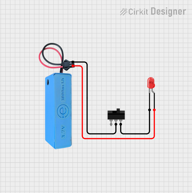 Open Project in Cirkit Designer
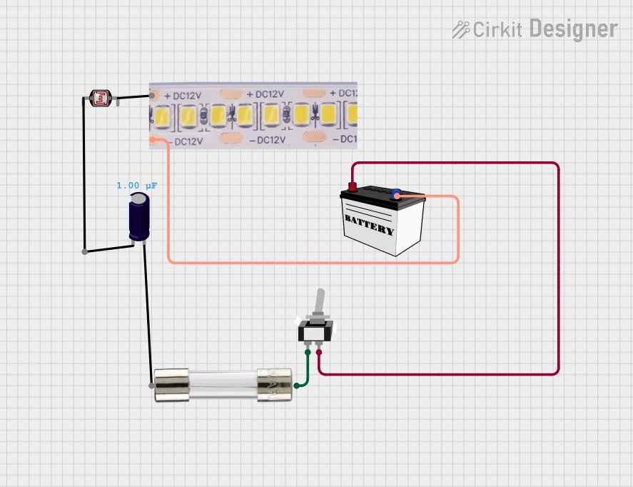 Open Project in Cirkit Designer
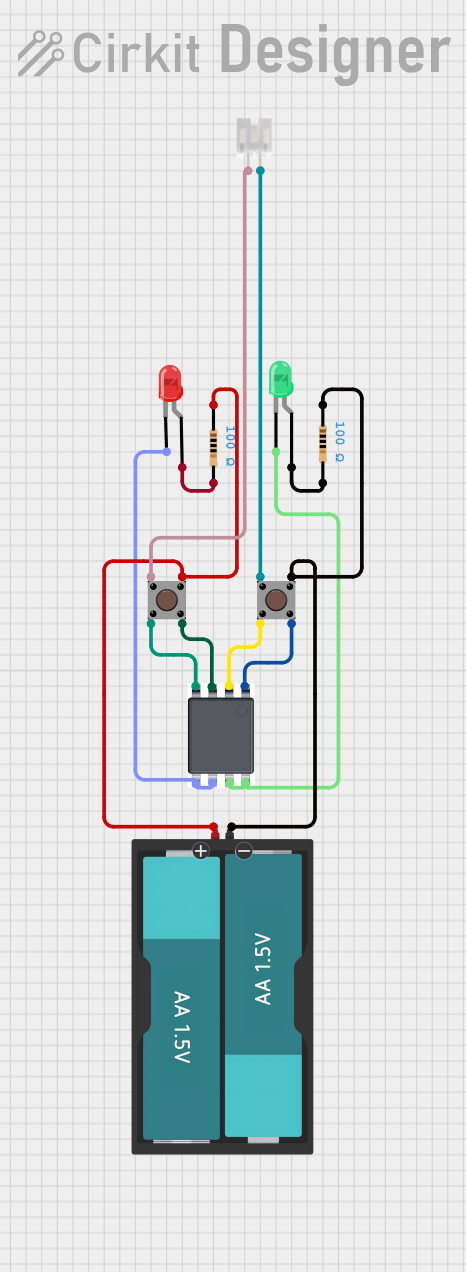 Open Project in Cirkit Designer
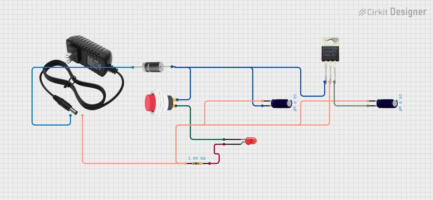 Open Project in Cirkit Designer
Explore Projects Built with Illuminated Tact LED Switch 12.7mm with supports
Open Project in Cirkit DesignerOpen Project in Cirkit DesignerOpen Project in Cirkit DesignerOpen Project in Cirkit DesignerCommon Applications
- Control panels for industrial and consumer electronics
- User interfaces for appliances and devices
- Status indication in embedded systems
- Prototyping and DIY electronics projects
Technical Specifications
Key Specifications
| Parameter | Value |
|---|---|
| Switch Type | Tactile push-button |
| LED Type | Integrated single-color LED |
| LED Voltage | 2.0V to 3.2V (typical) |
| LED Current | 20mA (maximum) |
| Switch Voltage Rating | 12V DC |
| Switch Current Rating | 50mA |
| Operating Temperature | -25°C to +70°C |
| Dimensions | 12.7mm x 12.7mm |
| Mounting Type | PCB through-hole with supports |
Pin Configuration and Descriptions
The Illuminated Tact LED Switch has four pins: two for the tactile switch and two for the LED. The pin configuration is as follows:
| Pin Number | Function | Description |
|---|---|---|
| 1 | LED Anode (+) | Positive terminal for the integrated LED |
| 2 | LED Cathode (-) | Negative terminal for the integrated LED |
| 3 | Switch Terminal 1 | One terminal of the tactile switch |
| 4 | Switch Terminal 2 | The other terminal of the tactile switch |
Note: The LED terminals are polarized and must be connected correctly to function.
Usage Instructions
How to Use the Component in a Circuit
Mounting the Switch:
- Insert the switch into the PCB through the designated through-hole pads.
- Ensure the supports are properly aligned with the PCB for secure mounting.
- Solder the pins and supports to the PCB for a stable connection.
Connecting the LED:
- Connect the LED Anode (Pin 1) to a current-limiting resistor, and then to the positive voltage supply.
- Connect the LED Cathode (Pin 2) to the ground (GND).
- Choose a resistor value that limits the current to 20mA or less, based on the supply voltage.
Connecting the Switch:
- Connect Switch Terminal 1 (Pin 3) to the input signal or microcontroller pin.
- Connect Switch Terminal 2 (Pin 4) to ground (GND) or the desired circuit path.
Example Circuit with Arduino UNO
Below is an example of how to connect the Illuminated Tact LED Switch to an Arduino UNO. The LED will light up when the switch is pressed, and the Arduino will detect the button press.
Circuit Diagram
- Pin 1 (LED Anode): Connect to a 220Ω resistor, then to Arduino 5V.
- Pin 2 (LED Cathode): Connect to Arduino GND.
- Pin 3 (Switch Terminal 1): Connect to Arduino digital pin 2.
- Pin 4 (Switch Terminal 2): Connect to Arduino GND.
Arduino Code
// Define pin connections
const int buttonPin = 2;  // Pin connected to the switch terminal
const int ledPin = 13;    // Built-in LED on Arduino for feedback

void setup() {
  pinMode(buttonPin, INPUT_PULLUP); // Set button pin as input with pull-up resistor
  pinMode(ledPin, OUTPUT);          // Set LED pin as output
}

void loop() {
  // Read the button state (LOW when pressed due to pull-up resistor)
  int buttonState = digitalRead(buttonPin);

  if (buttonState == LOW) {
    digitalWrite(ledPin, HIGH); // Turn on the Arduino LED
  } else {
    digitalWrite(ledPin, LOW);  // Turn off the Arduino LED
  }
}
Important Considerations
- Always use a current-limiting resistor with the LED to prevent damage.
- Ensure proper polarity when connecting the LED terminals.
- Use a pull-up or pull-down resistor with the switch to avoid floating inputs.
- Avoid exceeding the voltage and current ratings of the switch and LED.
Troubleshooting and FAQs
Common Issues and Solutions
LED Does Not Light Up:
- Cause: Incorrect polarity or missing current-limiting resistor.
- Solution: Verify the LED Anode and Cathode connections. Ensure a resistor is used.
Switch Not Detected by Microcontroller:
- Cause: Floating input or incorrect wiring.
- Solution: Use a pull-up or pull-down resistor on the microcontroller input pin.
Switch Feels Loose on PCB:
- Cause: Improper soldering or misaligned supports.
- Solution: Re-solder the pins and ensure the supports are properly seated.
LED Flickers When Pressing the Switch:
- Cause: Shared power supply or insufficient decoupling.
- Solution: Use separate power lines for the LED and switch, or add a decoupling capacitor.
FAQs
Q: Can I use this switch with a 3.3V system?
A: Yes, the LED can operate at 3.3V, but ensure the current-limiting resistor is adjusted accordingly.
Q: Is the LED color customizable?
A: The LED color depends on the specific model purchased. Check the product details for available colors.
Q: Can this switch handle AC voltage?
A: No, this switch is designed for DC voltage only. Using it with AC may damage the component.
Q: How do I clean the switch if it gets dirty?
A: Use a soft, dry cloth or compressed air. Avoid using liquids or abrasive materials.
This concludes the documentation for the Illuminated Tact LED Switch 12.7mm with Supports.