How to Use Adafruit USB LiPoly Charger: Examples, Pinouts, and Specs
Introduction
The Adafruit USB LiPoly Charger is a compact and efficient charging solution for single-cell lithium polymer (LiPo) batteries. This component is designed to charge LiPo batteries through a standard USB connection, making it ideal for portable electronics, DIY projects, and any application where reliable battery charging is required. Its ease of use and integration into existing projects make it a popular choice among hobbyists and professionals alike.
Explore Projects Built with Adafruit USB LiPoly Charger
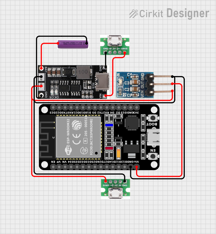


Explore Projects Built with Adafruit USB LiPoly Charger
Common Applications and Use Cases
- Portable electronic devices
- DIY electronics projects
- Remote control toys and drones
- Wearable technology
- Backup power supplies
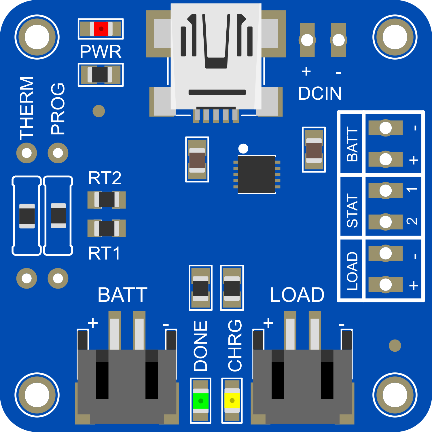
Technical Specifications
Key Technical Details
- Input Voltage: 5V via USB
- Charge Current: 100mA (default) or 500mA (selectable)
- Battery Voltage: 3.7V nominal (for single-cell LiPo batteries)
- Charge Cutoff: Automatic termination at 4.2V
- Indicator LEDs: Red for charging, green for charge complete
Pin Configuration and Descriptions
| Pin Number | Name | Description |
|---|---|---|
| 1 | BAT | Battery connection to LiPo positive terminal |
| 2 | GND | Ground connection |
| 3 | USB+ | USB power positive |
| 4 | USB- | USB power negative |
Usage Instructions
How to Use the Component in a Circuit
Connect the Battery:
- Connect the positive terminal of the LiPo battery to the
BATpin. - Connect the negative terminal of the LiPo battery to the
GNDpin.
- Connect the positive terminal of the LiPo battery to the
Power the Charger:
- Connect the
USB+andUSB-pins to a 5V USB power source.
- Connect the
Select Charge Current:
- The charger comes with a default setting of 100mA charge current.
- To select a higher charge current of 500mA, solder the closed jumper on the back of the PCB.
Monitor Charging:
- The red LED will illuminate to indicate that charging is in progress.
- Once the battery is fully charged, the green LED will light up, and the charger will automatically stop charging.
Important Considerations and Best Practices
- Ensure the polarity of the battery connections is correct to prevent damage.
- Do not exceed the recommended input voltage as it may damage the charger.
- Use the charger in a well-ventilated area and monitor during use.
- Do not leave the battery unattended while charging.
- Always disconnect the battery if the charger or battery becomes hot to the touch.
Troubleshooting and FAQs
Common Issues
Red LED does not illuminate when charging:
- Check the USB power source and connections.
- Ensure the battery is properly connected with correct polarity.
Green LED does not illuminate when expected:
- Verify that the battery is not already fully charged.
- Inspect the battery and charger for any signs of damage.
Solutions and Tips for Troubleshooting
- If the charger or battery becomes too hot, immediately disconnect and allow it to cool before inspecting.
- Ensure that the solder joints on the pins are well-made and free of cold solder joints or bridges.
- If the charging process seems to be taking too long, check the charge current setting and consider increasing it to 500mA if the battery can accept a higher charge rate.
FAQs
Can I charge batteries with a capacity higher than 500mAh?
- Yes, but charging will take longer since the maximum charge rate is 500mA.
Is it safe to leave the battery connected to the charger after charging is complete?
- The charger is designed to stop charging once the battery is full, but it is always best practice to disconnect the battery after charging to ensure safety.
Can I power the charger from a non-USB 5V source?
- Yes, as long as the voltage is regulated and does not exceed 5V.
Example Code for Arduino UNO
// No specific code is required for the Adafruit USB LiPoly Charger as it is a standalone charger.
// However, you can monitor the charging status using an Arduino by reading the status LEDs.

const int CHARGING_PIN = 2; // Connect to the charging LED pin on the charger
const int CHARGED_PIN = 3;  // Connect to the charged LED pin on the charger

void setup() {
  pinMode(CHARGING_PIN, INPUT);
  pinMode(CHARGED_PIN, INPUT);
  Serial.begin(9600);
}

void loop() {
  bool isCharging = digitalRead(CHARGING_PIN);
  bool isCharged = digitalRead(CHARGED_PIN);

  if (isCharging) {
    Serial.println("Battery is charging...");
  } else if (isCharged) {
    Serial.println("Battery is fully charged.");
  } else {
    Serial.println("Battery is not charging.");
  }

  delay(1000); // Wait for 1 second before checking again
}
Remember to connect the Arduino GND to the charger GND when making the LED connections. This code snippet is a simple way to integrate the charging status into an Arduino project for monitoring purposes.