How to Use VL53L1X: Examples, Pinouts, and Specs
Introduction
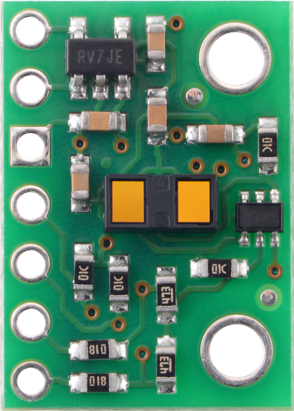
The VL53L1X is a time-of-flight (ToF) distance sensor manufactured by Pololu. It uses laser technology to measure distances with high accuracy and speed. This sensor can measure distances ranging from 30 mm to 4 meters, making it ideal for applications requiring precise distance measurement. The VL53L1X is compact, energy-efficient, and capable of operating in various lighting conditions, including complete darkness.
Explore Projects Built with VL53L1X


Explore Projects Built with VL53L1X
Common Applications
- Robotics for obstacle detection and navigation
- Drones for altitude measurement and collision avoidance
- Industrial automation for object detection
- Smart home devices for presence detection
- Consumer electronics for gesture recognition
Technical Specifications
The VL53L1X sensor offers advanced features and reliable performance. Below are its key technical specifications:
| Parameter | Value |
|---|---|
| Operating Voltage | 2.6 V to 3.5 V |
| Communication Interface | I²C |
| Measurement Range | 30 mm to 4 m |
| Accuracy | ±25 mm (typical) |
| Field of View (FoV) | Programmable, up to 27° |
| Maximum Sampling Rate | Up to 50 Hz |
| Operating Temperature | -20°C to +85°C |
| Dimensions | 4.9 mm × 2.5 mm × 1.56 mm |
Pin Configuration
The VL53L1X sensor module typically comes with the following pinout:
| Pin | Name | Description |
|---|---|---|
| 1 | VIN | Power supply input (2.6 V to 5.5 V) |
| 2 | GND | Ground connection |
| 3 | SDA | I²C data line |
| 4 | SCL | I²C clock line |
| 5 | XSHUT | Shutdown pin (active low, used to reset or disable the sensor) |
| 6 | GPIO1 | Interrupt output (optional, configurable for advanced use cases) |
Usage Instructions
The VL53L1X is straightforward to integrate into a circuit, especially with microcontrollers like the Arduino UNO. Below are the steps to use the sensor effectively:
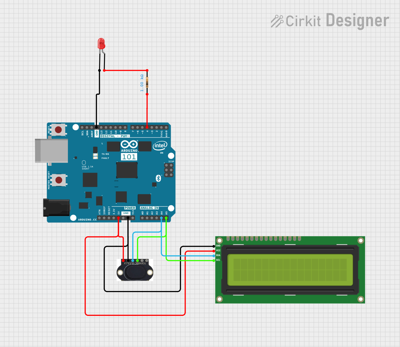
Connecting the VL53L1X to an Arduino UNO
- Power the Sensor: Connect the
VINpin to the Arduino's 5V pin and theGNDpin to the Arduino's GND. - I²C Communication: Connect the
SDApin to the Arduino's A4 pin and theSCLpin to the Arduino's A5 pin. - Optional Connections:
- Connect the
XSHUTpin to a digital pin on the Arduino if you need to reset or disable the sensor. - Use the
GPIO1pin for interrupt-based applications if required.
- Connect the
Sample Arduino Code
Below is an example of how to use the VL53L1X with an Arduino UNO. This code uses the Pololu VL53L1X library, which can be installed via the Arduino Library Manager.
#include <Wire.h>
#include <VL53L1X.h>

// Create an instance of the VL53L1X sensor
VL53L1X sensor;

void setup() {
  Serial.begin(9600); // Initialize serial communication
  Wire.begin();       // Initialize I²C communication

  // Initialize the VL53L1X sensor
  sensor.setTimeout(500); // Set timeout for sensor operations
  if (!sensor.init()) {
    Serial.println("Failed to initialize VL53L1X sensor!");
    while (1); // Halt execution if initialization fails
  }

  // Configure the sensor
  sensor.setDistanceMode(VL53L1X::Long); // Set distance mode to Long
  sensor.setMeasurementTimingBudget(50000); // Set timing budget to 50 ms
  sensor.startContinuous(50); // Start continuous measurements every 50 ms
}

void loop() {
  // Read distance measurement
  uint16_t distance = sensor.read();
  if (sensor.timeoutOccurred()) {
    Serial.println("Sensor timeout occurred!");
  } else {
    Serial.print("Distance: ");
    Serial.print(distance);
    Serial.println(" mm");
  }

  delay(100); // Delay to avoid flooding the serial monitor
}
Important Considerations
- Power Supply: Ensure the sensor operates within its voltage range (2.6 V to 3.5 V). If using a 5V system, a voltage regulator or level shifter may be required.
- I²C Address: The default I²C address of the VL53L1X is
0x29. If using multiple sensors, you must configure unique addresses for each. - Field of View: The sensor's field of view can be adjusted programmatically to suit your application.
- Ambient Light: While the sensor works in various lighting conditions, excessive ambient light may reduce accuracy.
Troubleshooting and FAQs
Common Issues
Sensor Not Detected on I²C Bus:
- Ensure the
SDAandSCLlines are correctly connected. - Verify pull-up resistors are present on the I²C lines (if not already included on the module).
- Check the sensor's power supply voltage.
- Ensure the
Inaccurate Distance Measurements:
- Ensure there are no reflective surfaces near the sensor that could interfere with measurements.
- Verify the sensor is not tilted or misaligned relative to the target.
Timeout Errors:
- Increase the timeout value in the code using
sensor.setTimeout(). - Check for loose connections or excessive noise on the I²C lines.
- Increase the timeout value in the code using
FAQs
Q: Can the VL53L1X measure distances beyond 4 meters?
A: No, the maximum range of the VL53L1X is 4 meters. For longer ranges, consider other ToF sensors.
Q: How do I use multiple VL53L1X sensors on the same I²C bus?
A: Use the XSHUT pin to reset individual sensors and assign unique I²C addresses programmatically.
Q: Does the sensor work in complete darkness?
A: Yes, the VL53L1X uses an infrared laser for measurements and does not rely on ambient light.
Q: Can I use the VL53L1X with a 5V microcontroller?
A: Yes, but you must use a voltage regulator or level shifter to ensure the sensor operates within its voltage range.
By following this documentation, you can effectively integrate and use the VL53L1X sensor in your projects.