How to Use Battery charger control: Examples, Pinouts, and Specs
Introduction
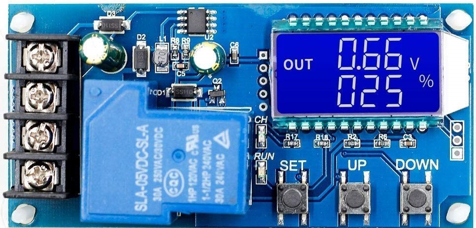
The XY-L30A is a battery charger control module manufactured by Techtonics. It is designed to manage the charging process of batteries, ensuring efficient and safe charging by regulating voltage and current. This component is ideal for use in applications requiring precise battery management, such as power banks, solar charging systems, and uninterruptible power supplies (UPS).
Explore Projects Built with Battery charger control

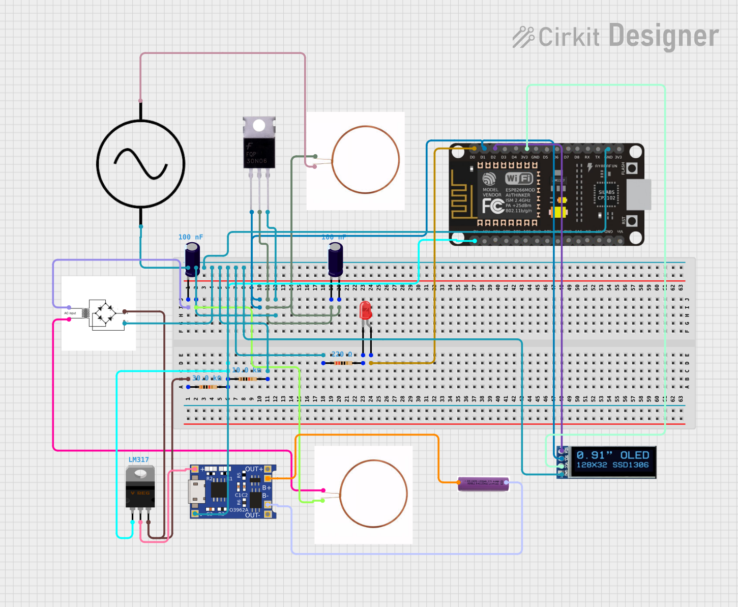
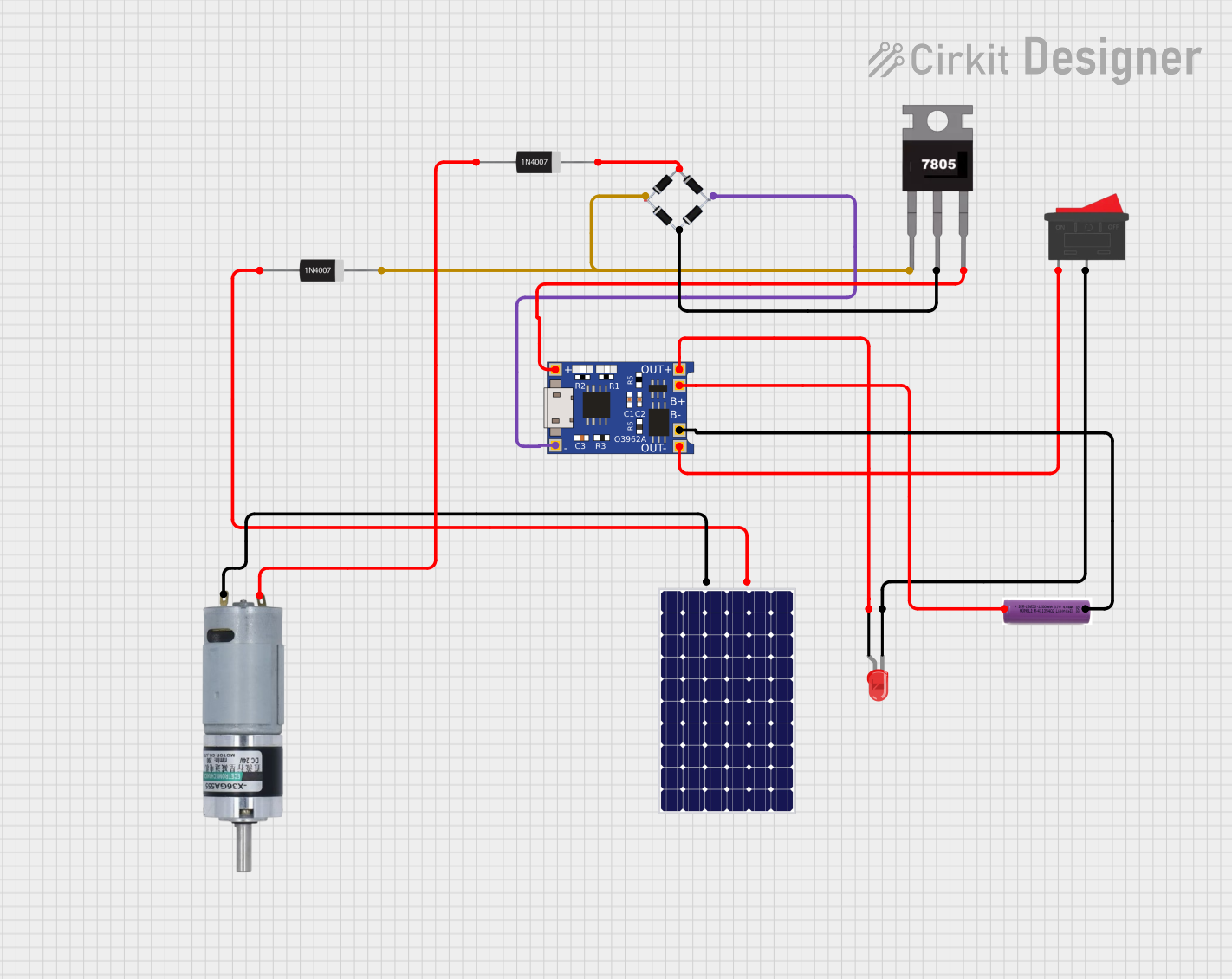
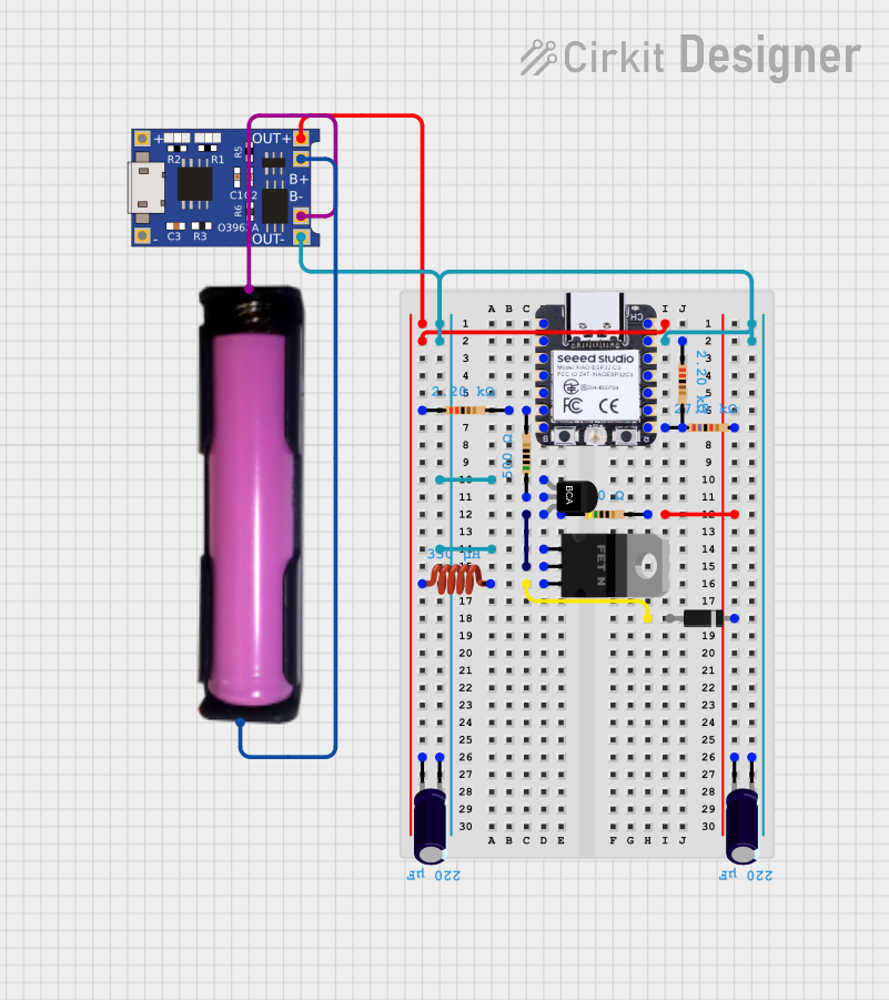
Explore Projects Built with Battery charger control
Common Applications and Use Cases
- Lithium-ion and lead-acid battery charging
- Solar-powered battery systems
- DIY power supply projects
- Battery backup systems
- Electric vehicles and portable electronics
Technical Specifications
The following table outlines the key technical details of the XY-L30A battery charger control module:
| Parameter | Specification |
|---|---|
| Input Voltage Range | 6V to 60V |
| Output Voltage Range | 0V to 60V |
| Maximum Output Current | 30A |
| Output Power | Up to 600W |
| Voltage Accuracy | ±0.1V |
| Current Accuracy | ±0.1A |
| Display Type | Digital LED |
| Protection Features | Over-voltage, over-current, |
| over-temperature, and short-circuit | |
| Dimensions | 79mm x 43mm x 38mm |
Pin Configuration and Descriptions
The XY-L30A module has the following input and output terminals:
| Pin/Terminal | Description |
|---|---|
| VIN+ | Positive input terminal for the power supply (6V to 60V). |
| VIN- | Negative input terminal for the power supply (ground). |
| VOUT+ | Positive output terminal for connecting to the battery or load. |
| VOUT- | Negative output terminal for connecting to the battery or load. |
| SET Button | Used to configure voltage, current, and protection parameters. |
| ON/OFF Button | Enables or disables the output. |
Usage Instructions
How to Use the XY-L30A in a Circuit
Connect the Input Power Supply:
- Connect the positive terminal of the power supply to
VIN+and the negative terminal toVIN-. Ensure the input voltage is within the 6V to 60V range.
- Connect the positive terminal of the power supply to
Connect the Battery or Load:
- Attach the battery or load to the
VOUT+andVOUT-terminals. Ensure the battery's voltage and current ratings are compatible with the module's output.
- Attach the battery or load to the
Set the Charging Parameters:
- Press the
SETbutton to configure the desired output voltage and current. Use the digital display to monitor the settings.
- Press the
Enable the Output:
- Press the
ON/OFFbutton to start the charging process. The module will regulate the voltage and current to safely charge the battery.
- Press the
Monitor the Charging Process:
- Use the LED display to monitor real-time voltage, current, and power. The module will automatically stop charging when the battery is fully charged.
Important Considerations and Best Practices
- Input Voltage: Ensure the input voltage is at least 2V higher than the desired output voltage for proper operation.
- Heat Dissipation: The module may generate heat during operation. Use a heatsink or active cooling if operating at high currents.
- Protection Settings: Configure over-voltage, over-current, and over-temperature protection to safeguard the battery and module.
- Battery Compatibility: Verify that the battery type (e.g., lithium-ion, lead-acid) is compatible with the module's charging profile.
Example: Using the XY-L30A with an Arduino UNO
The XY-L30A can be used with an Arduino UNO to monitor the charging process. Below is an example code to read the voltage and current using an analog-to-digital converter (ADC):
// Example code to monitor voltage and current using Arduino UNO
// Connect the VOUT+ and VOUT- terminals to the Arduino's ADC pins

const int voltagePin = A0; // Pin connected to voltage output
const int currentPin = A1; // Pin connected to current output
const float voltageDividerRatio = 10.0; // Adjust based on your voltage divider
const float currentSenseResistor = 0.01; // Value of current sense resistor in ohms

void setup() {
  Serial.begin(9600); // Initialize serial communication
  pinMode(voltagePin, INPUT);
  pinMode(currentPin, INPUT);
}

void loop() {
  // Read voltage and current values
  int rawVoltage = analogRead(voltagePin);
  int rawCurrent = analogRead(currentPin);

  // Convert raw ADC values to actual voltage and current
  float voltage = (rawVoltage * 5.0 / 1023.0) * voltageDividerRatio;
  float current = (rawCurrent * 5.0 / 1023.0) / currentSenseResistor;

  // Print the values to the Serial Monitor
  Serial.print("Voltage: ");
  Serial.print(voltage);
  Serial.println(" V");

  Serial.print("Current: ");
  Serial.print(current);
  Serial.println(" A");

  delay(1000); // Wait for 1 second before the next reading
}
Troubleshooting and FAQs
Common Issues and Solutions
No Output Voltage:
- Ensure the input power supply is connected and within the specified voltage range.
- Verify that the output is enabled by pressing the
ON/OFFbutton.
Overheating:
- Check if the module is operating at high currents. Use a heatsink or fan for cooling.
- Ensure proper ventilation around the module.
Inaccurate Voltage or Current Readings:
- Recalibrate the module if necessary.
- Verify the connections and ensure there is no loose wiring.
Module Shuts Down Automatically:
- Check the protection settings for over-voltage, over-current, or over-temperature.
- Ensure the battery or load is within the module's operating range.
FAQs
Q: Can the XY-L30A charge multiple batteries in series?
A: Yes, but ensure the total voltage of the batteries does not exceed the module's output voltage range.
Q: Is the module compatible with lithium-ion batteries?
A: Yes, the XY-L30A is compatible with lithium-ion, lead-acid, and other rechargeable batteries.
Q: How do I reset the module to factory settings?
A: Press and hold the SET button for 5 seconds to reset the module to its default configuration.
Q: Can I use the module as a constant current power supply?
A: Yes, the XY-L30A can be configured to operate in constant current mode for powering devices.
By following this documentation, users can effectively utilize the XY-L30A battery charger control module for a wide range of applications.