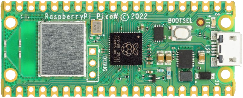
How to Use PicoW: Examples, Pinouts, and Specs
Introduction
The PicoWatt (pW) is a unit of power measurement that represents one trillionth of a watt (1 pW = 10^-12 W). This extremely small unit is used in electronics, photonics, and telecommunications to quantify very low power levels, such as those found in signal processing or in the operation of sensitive sensors. Understanding and measuring power at the picoWatt level is crucial for applications that require high precision and low power consumption.
Common applications of picoWatt-level measurements include:
- Optical fiber communication systems
- Nanotechnology and microelectromechanical systems (MEMS)
- Low-power integrated circuits
- Quantum computing and cryptography
- Biomedical sensors and devices
Explore Projects Built with PicoW
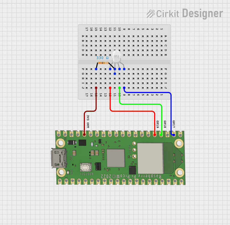
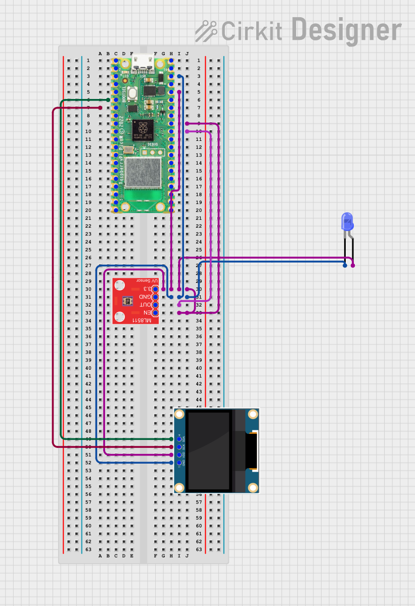
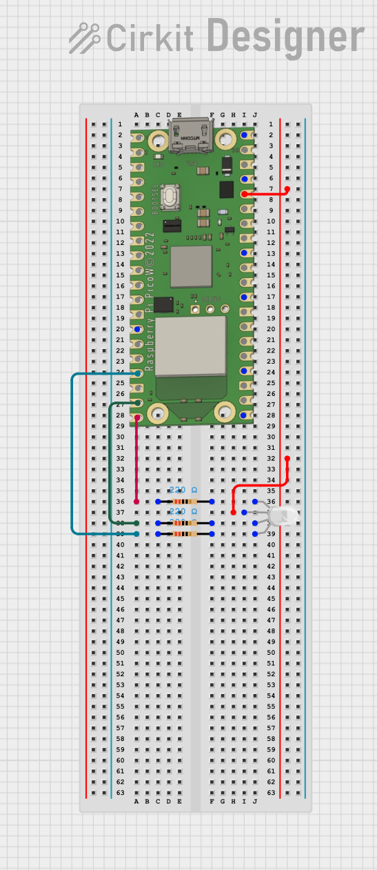
Explore Projects Built with PicoW
Technical Specifications
Since the PicoW is a unit of measurement rather than a specific electronic component, it does not have technical specifications like voltage or current ratings. However, when working with electronic components that operate at picoWatt power levels, it is essential to consider the sensitivity and accuracy of measurement equipment.
Measurement Equipment Specifications
| Specification | Description |
|---|---|
| Sensitivity | The minimum power level that can be accurately measured, often in the pW range. |
| Accuracy | The degree to which the measurement is close to the actual power level, typically expressed as a percentage. |
| Frequency Range | The range of frequencies over which the equipment can accurately measure power, important for RF applications. |
| Dynamic Range | The ratio between the smallest and largest power levels that the equipment can measure. |
Usage Instructions
Measuring picoWatt Power Levels
- Select Appropriate Equipment: Choose measurement equipment that can detect power levels in the picoWatt range with high accuracy.
- Calibration: Ensure that the equipment is properly calibrated to maintain measurement accuracy.
- Environmental Considerations: Minimize external influences such as temperature, electromagnetic interference, and vibration that could affect measurements.
- Connection and Setup: Connect the equipment according to the manufacturer's instructions, ensuring that all connections are secure and free from interference.
- Data Acquisition: Collect data using the equipment's interface, taking multiple readings if necessary to ensure reliability.
Best Practices
- Use shielded cables and enclosures to reduce noise.
- Avoid overloading the measurement equipment to prevent damage and inaccurate readings.
- Regularly calibrate and maintain the equipment to ensure ongoing accuracy.
- Document measurement conditions and parameters for repeatability.
Troubleshooting and FAQs
Common Issues
- Inaccurate Readings: Ensure the equipment is calibrated and that environmental factors are controlled.
- Noise and Interference: Use shielding and grounding techniques to minimize external influences.
- Equipment Overload: Verify that the power levels are within the equipment's dynamic range.
FAQs
Q: How can I improve the accuracy of picoWatt measurements? A: Use high-quality, calibrated equipment, maintain a controlled measurement environment, and follow best practices for noise reduction.
Q: What is the significance of measuring power in the picoWatt range? A: Measuring power at this level is crucial for applications that require low power consumption and high precision, such as in advanced communication systems and sensitive sensors.
Q: Can I measure picoWatt power levels with a standard multimeter? A: No, standard multimeters are not sensitive enough to measure power at the picoWatt level. Specialized equipment is required.
Q: Are there any safety concerns when measuring picoWatt power levels? A: Safety concerns are minimal due to the extremely low power levels involved. However, handling and operating sensitive equipment should always be done with care.
Please note that this documentation is a general guide on the picoWatt as a unit of measurement. For specific components or systems operating at picoWatt levels, refer to the manufacturer's datasheets and technical documents for detailed information and instructions.