How to Use SIM808 GSM GPS GPRS module: Examples, Pinouts, and Specs
Introduction
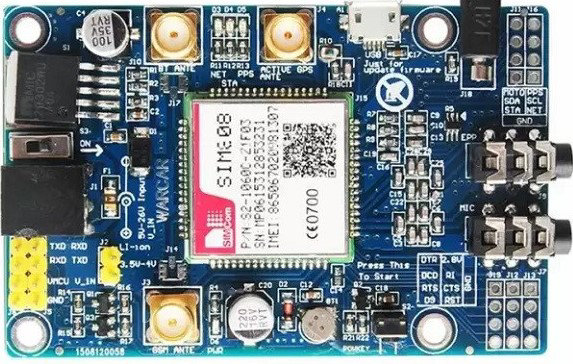
The SIM808 module is a versatile electronic component that combines GSM, GPS, and GPRS functionalities. This integration allows for mobile communication, location tracking, and data transmission, making it an ideal choice for a wide range of applications. Common use cases include vehicle tracking systems, remote data logging, IoT projects, and mobile communication devices.
Explore Projects Built with SIM808 GSM GPS GPRS module
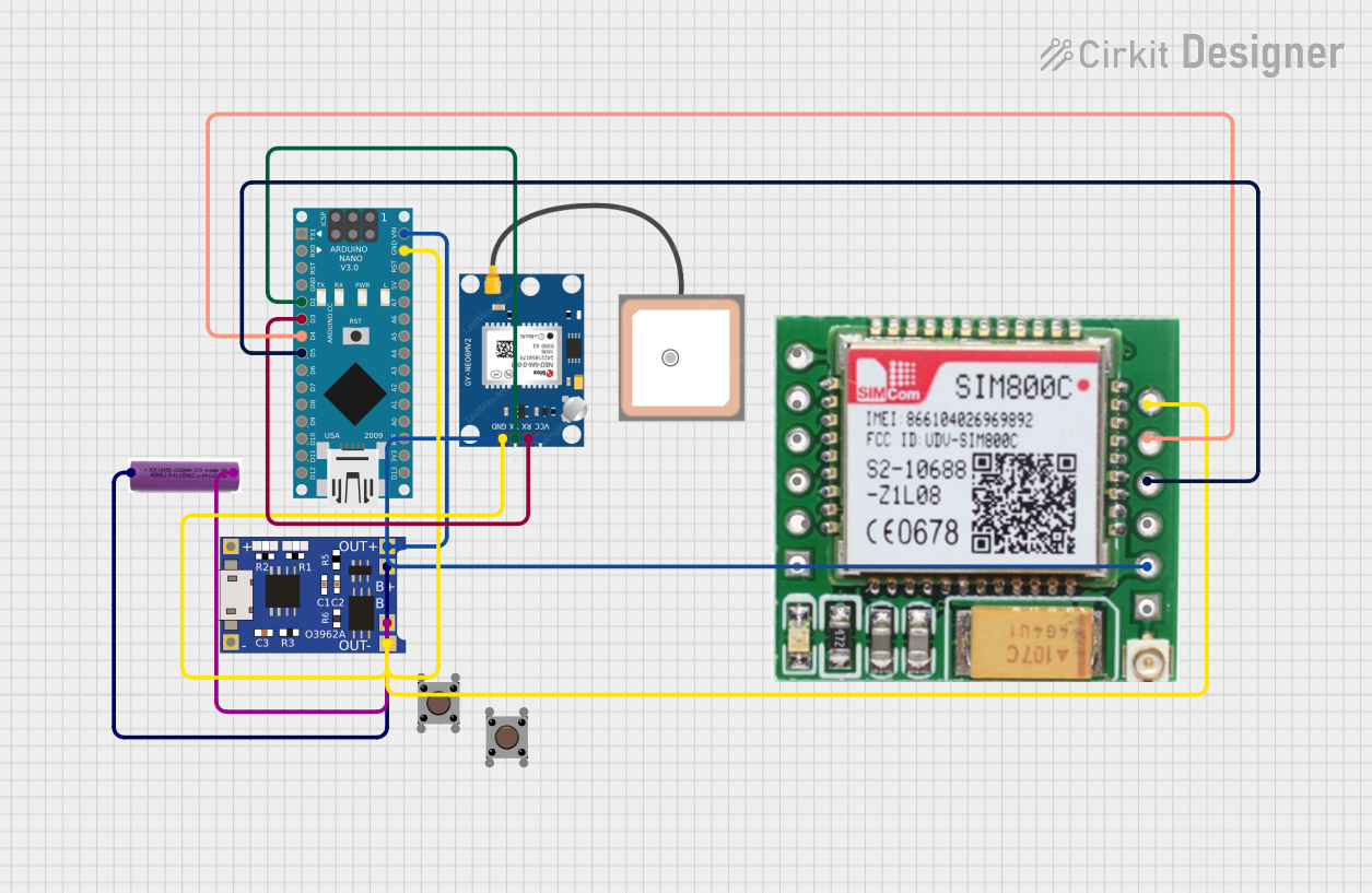
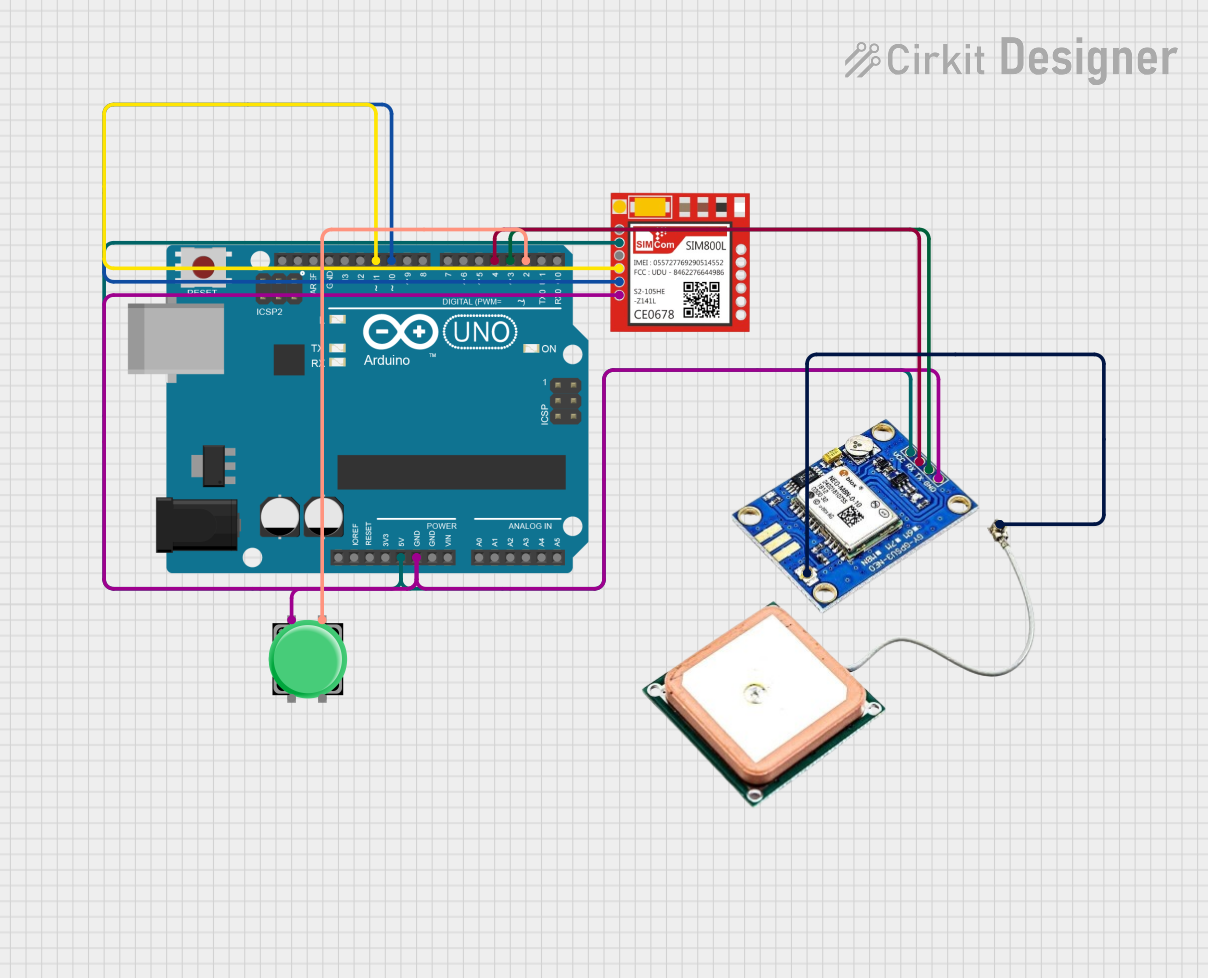
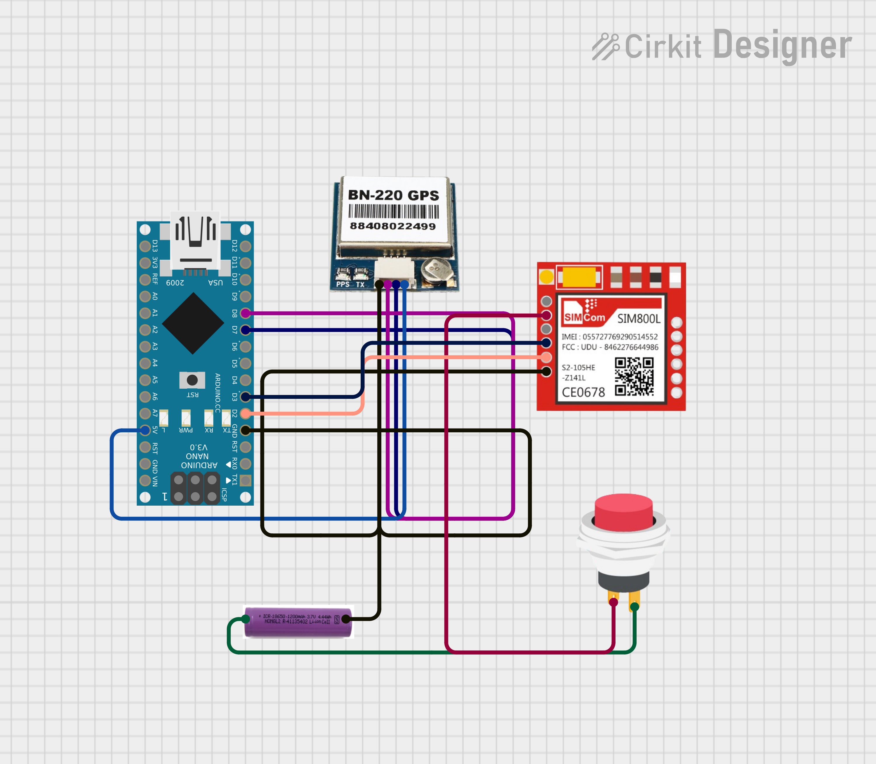
Explore Projects Built with SIM808 GSM GPS GPRS module
Technical Specifications
Key Technical Details
| Parameter | Value |
|---|---|
| Operating Voltage | 3.4V - 4.4V |
| Operating Current | 1.0A (peak), 20mA (idle) |
| GSM Frequency | 850/900/1800/1900 MHz |
| GPS Sensitivity | -165 dBm |
| GPRS Multi-slot | Class 12 |
| GPS Channels | 22 |
| Data Transmission | GPRS, SMS, Voice |
| Interface | UART, SPI, I2C |
| Dimensions | 30mm x 30mm x 3mm |
Pin Configuration and Descriptions
| Pin Number | Pin Name | Description |
|---|---|---|
| 1 | VCC | Power supply (3.4V - 4.4V) |
| 2 | GND | Ground |
| 3 | TXD | UART Transmit Data |
| 4 | RXD | UART Receive Data |
| 5 | DTR | Data Terminal Ready |
| 6 | RST | Reset |
| 7 | NET | Network status indicator |
| 8 | GPS_TX | GPS UART Transmit Data |
| 9 | GPS_RX | GPS UART Receive Data |
| 10 | PWRKEY | Power on/off control |
| 11 | MIC+ | Microphone positive input |
| 12 | MIC- | Microphone negative input |
| 13 | SPK+ | Speaker positive output |
| 14 | SPK- | Speaker negative output |
Usage Instructions
How to Use the SIM808 Module in a Circuit
- Power Supply: Connect the VCC pin to a stable 3.4V - 4.4V power source and the GND pin to the ground.
- UART Communication: Connect the TXD pin to the RX pin of your microcontroller (e.g., Arduino UNO) and the RXD pin to the TX pin of your microcontroller.
- Power Control: To turn on the module, connect the PWRKEY pin to the ground for at least 1 second.
- GPS Functionality: Connect the GPS_TX and GPS_RX pins to the corresponding UART pins of your microcontroller if you need GPS data.
- Antenna: Attach the GSM and GPS antennas to their respective connectors on the module.
Important Considerations and Best Practices
- Power Supply: Ensure a stable power supply to avoid unexpected resets or malfunctions.
- Antenna Placement: Place the antennas in a location with minimal obstructions for better signal reception.
- UART Baud Rate: Configure the UART baud rate to match the module's default setting (usually 9600 bps).
- Heat Dissipation: Provide adequate ventilation to prevent overheating during prolonged use.
Sample Arduino Code
#include <SoftwareSerial.h>

// Create a software serial port on pins 7 (RX) and 8 (TX)
SoftwareSerial sim808(7, 8);

void setup() {
  // Start communication with the SIM808 module at 9600 baud
  sim808.begin(9600);
  Serial.begin(9600);

  // Power on the module
  pinMode(9, OUTPUT);
  digitalWrite(9, LOW);
  delay(1000);
  digitalWrite(9, HIGH);
  delay(2000);
  digitalWrite(9, LOW);

  // Wait for the module to initialize
  delay(5000);

  // Send an AT command to check communication
  sim808.println("AT");
  delay(1000);

  // Read and print the response from the module
  while (sim808.available()) {
    Serial.write(sim808.read());
  }
}

void loop() {
  // Continuously read data from the SIM808 module and print it to the serial monitor
  if (sim808.available()) {
    Serial.write(sim808.read());
  }

  // Continuously read data from the serial monitor and send it to the SIM808 module
  if (Serial.available()) {
    sim808.write(Serial.read());
  }
}
Troubleshooting and FAQs
Common Issues and Solutions
Module Not Responding:
- Solution: Ensure the power supply is stable and within the specified range. Check the PWRKEY pin connection and ensure it is correctly toggled.
Poor Signal Reception:
- Solution: Verify that the antennas are properly connected and placed in an optimal location. Check for any physical obstructions that may be blocking the signal.
GPS Data Not Received:
- Solution: Ensure the GPS_TX and GPS_RX pins are correctly connected to the microcontroller. Verify that the module has a clear view of the sky for better satellite reception.
Communication Issues:
- Solution: Check the UART connections and ensure the baud rate is correctly set. Use a logic level converter if interfacing with a 5V microcontroller.
FAQs
Q: Can the SIM808 module be powered with a 5V supply?
- A: No, the module requires a power supply within the range of 3.4V to 4.4V.
Q: How do I reset the module?
- A: Toggle the RST pin to the ground for a brief moment to reset the module.
Q: What is the default baud rate for UART communication?
- A: The default baud rate is 9600 bps.
Q: Can I use the SIM808 module for voice calls?
- A: Yes, the module supports voice calls. Connect a microphone and speaker to the MIC+/- and SPK+/- pins, respectively.
This documentation provides a comprehensive guide to using the SIM808 GSM GPS GPRS module, ensuring both beginners and experienced users can effectively integrate it into their projects.