How to Use Analog VTX: Examples, Pinouts, and Specs
Introduction
An Analog Video Transmitter (VTX) is a critical component in video transmission systems, particularly in FPV (First Person View) applications such as drone racing, aerial photography, and remote-controlled vehicles. It is responsible for transmitting live video signals from a camera to a receiver, enabling real-time video streaming. Analog VTXs are favored for their low latency, simplicity, and compatibility with a wide range of devices.
Explore Projects Built with Analog VTX
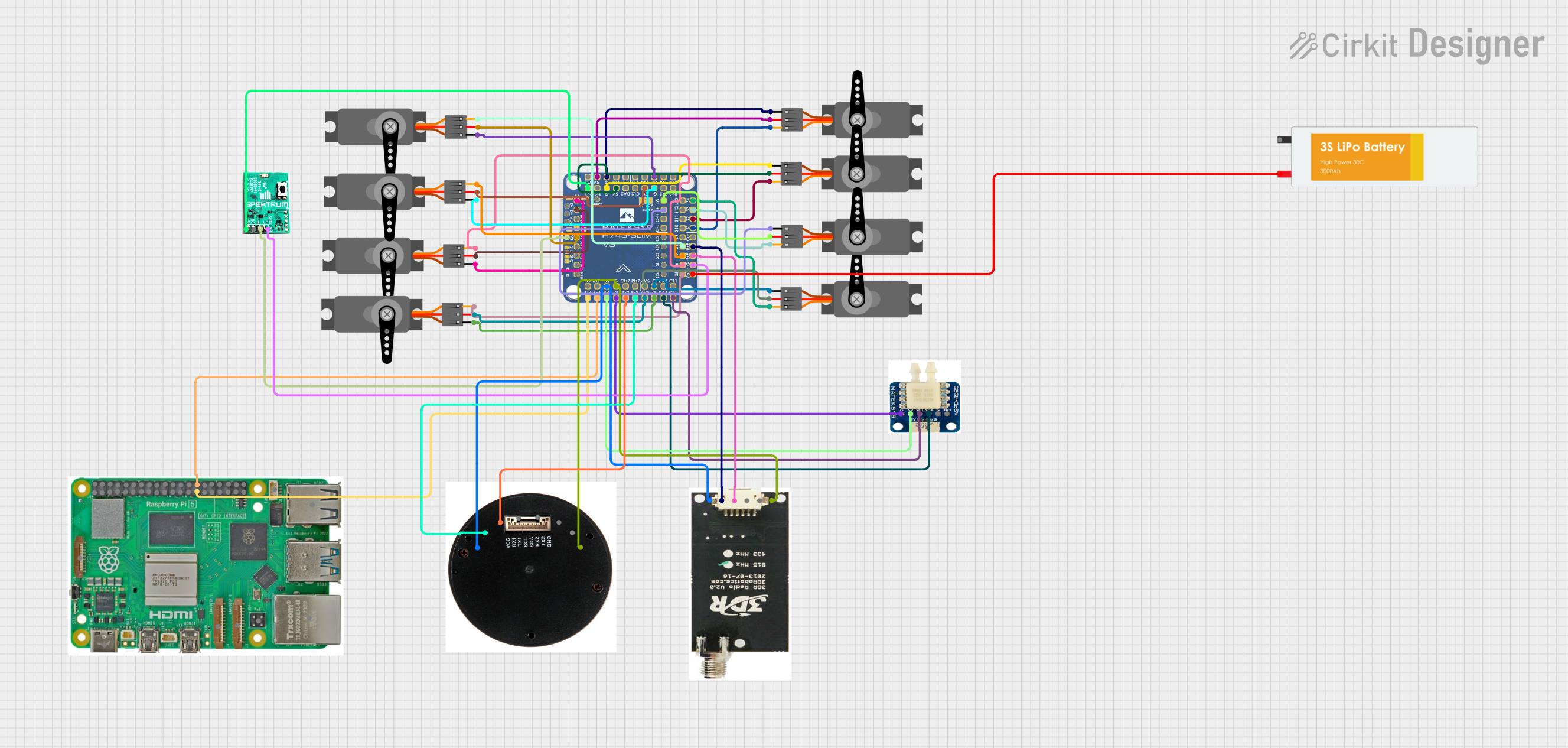

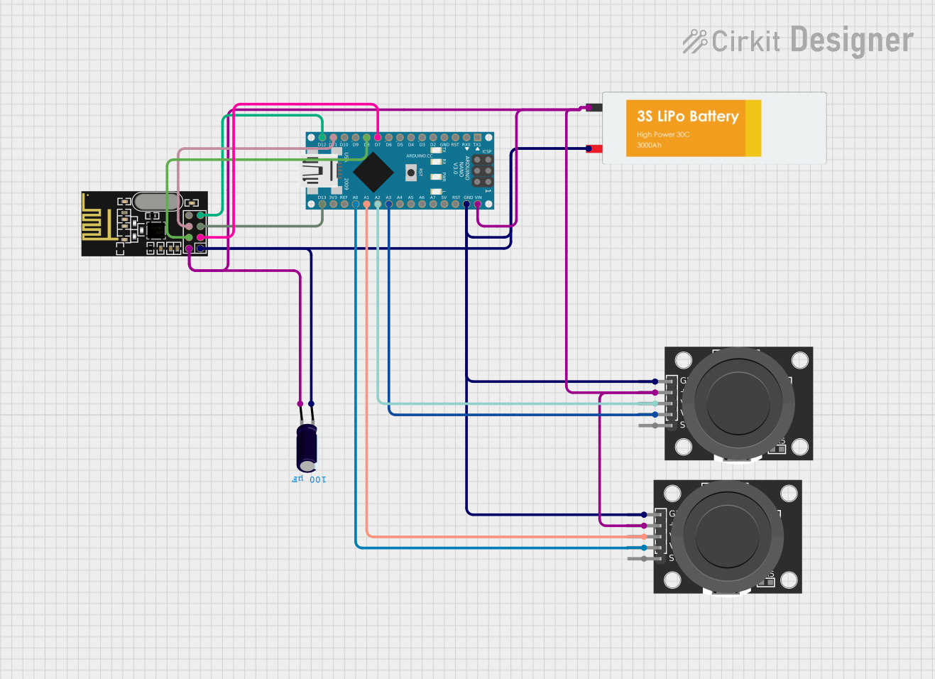

Explore Projects Built with Analog VTX
Common Applications and Use Cases
- FPV drone racing for real-time video feedback.
- Aerial photography and videography for live monitoring.
- Remote-controlled vehicles and robotics for navigation.
- Security and surveillance systems for wireless video transmission.
Technical Specifications
Below are the key technical details and pin configuration for a typical Analog VTX:
Key Technical Details
- Input Voltage: 5V to 26V (varies by model)
- Output Power: 25mW, 200mW, 500mW, or 1W (adjustable on some models)
- Frequency Bands: 5.8 GHz (common), with 40+ channels
- Video Format: NTSC/PAL
- Connector Types: SMA or RP-SMA for antenna, JST or solder pads for power
- Latency: < 10ms
- Operating Temperature: -10°C to 60°C
- Weight: Typically 5g to 15g (excluding antenna)
Pin Configuration and Descriptions
The pin configuration may vary depending on the model, but a typical Analog VTX has the following pins:
| Pin | Label | Description |
|---|---|---|
| 1 | VCC (+) | Power input (5V to 26V, depending on the VTX model). |
| 2 | GND (-) | Ground connection. |
| 3 | VIDEO IN | Analog video input from the camera. |
| 4 | AUDIO IN (optional) | Audio input for transmitting audio signals (if supported). |
| 5 | SMART AUDIO (optional) | Control input for changing VTX settings via a flight controller or transmitter. |
| 6 | ANTENNA | RF output for connecting the antenna (via SMA or RP-SMA connector). |
Usage Instructions
How to Use the Analog VTX in a Circuit
- Power Connection: Connect the VCC pin to a regulated power source (e.g., 5V or 12V, depending on the VTX model). Ensure the power source can supply sufficient current for the VTX's power output setting.
- Ground Connection: Connect the GND pin to the ground of your power source.
- Video Input: Connect the VIDEO IN pin to the video output of your camera. Ensure the camera's video format (NTSC or PAL) matches the VTX's supported format.
- Antenna: Attach a compatible antenna to the VTX's antenna connector. Always connect the antenna before powering on the VTX to avoid damage.
- Optional Connections:
- If your VTX supports audio transmission, connect an audio source to the AUDIO IN pin.
- If your VTX supports Smart Audio, connect the SMART AUDIO pin to the flight controller for remote configuration.
Important Considerations and Best Practices
- Antenna Connection: Never power on the VTX without an antenna connected, as this can damage the transmitter.
- Frequency Selection: Use a frequency that complies with local regulations and avoids interference with other devices.
- Cooling: Analog VTXs can generate significant heat, especially at higher power levels. Ensure proper airflow or use a heat sink to prevent overheating.
- Range Testing: Test the video transmission range in an open area to ensure reliable performance.
- Smart Audio Configuration: If using Smart Audio, configure the VTX settings (e.g., frequency, power level) via your flight controller or transmitter.
Example: Connecting an Analog VTX to an Arduino UNO
While Analog VTXs are not typically controlled by an Arduino, you can use an Arduino to send Smart Audio commands to configure the VTX. Below is an example code snippet:
#include <SoftwareSerial.h>

// Define Smart Audio pin
#define SMART_AUDIO_PIN 10

// Initialize SoftwareSerial for Smart Audio communication
SoftwareSerial smartAudio(SMART_AUDIO_PIN, -1); // RX only

void setup() {
  // Start serial communication for debugging
  Serial.begin(9600);
  Serial.println("Initializing Smart Audio...");

  // Start Smart Audio communication
  smartAudio.begin(9600);
}

void loop() {
  // Example: Send a command to set VTX frequency (replace with actual command)
  byte setFrequencyCommand[] = {0xAA, 0x55, 0x03, 0x01, 0xE0};
  // Replace with the correct command for your VTX model

  // Send the command
  smartAudio.write(setFrequencyCommand, sizeof(setFrequencyCommand));
  Serial.println("Frequency command sent!");

  // Wait for a response (if applicable)
  delay(1000);
}
Note: Refer to your VTX's Smart Audio protocol documentation for the correct command structure.
Troubleshooting and FAQs
Common Issues and Solutions
No Video Signal:
- Ensure the camera is powered and connected to the VIDEO IN pin.
- Verify the VTX is powered and the antenna is connected.
- Check that the receiver is tuned to the same frequency as the VTX.
Overheating:
- Reduce the VTX power output if possible.
- Improve airflow or add a heat sink to the VTX.
Interference or Poor Signal Quality:
- Change the VTX frequency to avoid interference with other devices.
- Use a high-quality antenna and ensure it is securely connected.
Smart Audio Not Working:
- Verify the SMART AUDIO pin is correctly connected to the flight controller.
- Check the Smart Audio protocol version supported by your VTX and flight controller.
FAQs
Q: Can I use an Analog VTX without a receiver?
A: No, you need a compatible receiver to view the transmitted video signal.Q: What is the maximum range of an Analog VTX?
A: The range depends on the power output, antenna quality, and environmental conditions. Typical ranges are 500m to 5km.Q: Can I use an Analog VTX indoors?
A: Yes, but the range may be limited due to walls and other obstacles causing signal attenuation.Q: How do I change the VTX frequency?
A: Use the onboard buttons or Smart Audio (if supported) to select the desired frequency.
By following this documentation, you can effectively integrate and troubleshoot an Analog VTX in your projects.