How to Use Step Down DC/DC Buck Converter 12V/24V to 7.5V 10A: Examples, Pinouts, and Specs
Introduction
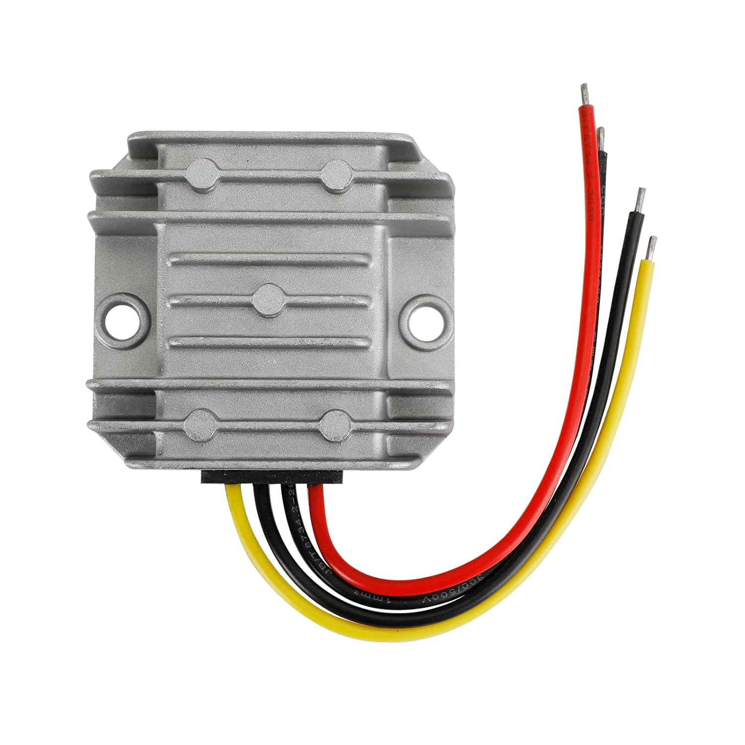
The Step Down DC/DC Buck Converter 12V/24V to 7.5V 10A is a high-efficiency voltage regulator designed to step down a higher DC input voltage (12V or 24V) to a stable 7.5V output. With a maximum output current of 10A, this converter is ideal for powering devices that require a lower voltage, such as microcontrollers, sensors, LED strips, and other electronic devices. Its compact design and high current capacity make it suitable for automotive, industrial, and hobbyist applications.
Explore Projects Built with Step Down DC/DC Buck Converter 12V/24V to 7.5V 10A


Explore Projects Built with Step Down DC/DC Buck Converter 12V/24V to 7.5V 10A
Common Applications and Use Cases
- Powering 7.5V devices from a 12V or 24V power source
- Automotive electronics (e.g., powering dashboard devices or auxiliary systems)
- Industrial control systems
- Robotics and IoT projects
- LED lighting systems
- Battery-powered systems requiring efficient voltage regulation
Technical Specifications
The following table outlines the key technical details of the Step Down DC/DC Buck Converter:
| Parameter | Value |
|---|---|
| Input Voltage Range | 12V to 24V DC |
| Output Voltage | 7.5V DC |
| Maximum Output Current | 10A |
| Efficiency | Up to 95% (depending on load) |
| Operating Temperature | -40°C to +85°C |
| Dimensions | Varies by model (e.g., 60x40x20mm) |
| Protection Features | Overcurrent, Overtemperature, |
| and Short-Circuit Protection |
Pin Configuration and Descriptions
The converter typically has four connection points, as described below:
| Pin | Label | Description |
|---|---|---|
| 1 | VIN+ | Positive input voltage terminal (12V or 24V DC) |
| 2 | VIN- | Negative input voltage terminal (ground) |
| 3 | VOUT+ | Positive output voltage terminal (7.5V DC) |
| 4 | VOUT- | Negative output voltage terminal (ground) |
Usage Instructions
How to Use the Component in a Circuit
Connect the Input Voltage:
- Connect the VIN+ pin to the positive terminal of your 12V or 24V DC power source.
- Connect the VIN- pin to the ground (negative terminal) of your power source.
Connect the Output Voltage:
- Connect the VOUT+ pin to the positive terminal of the load (e.g., a 7.5V device).
- Connect the VOUT- pin to the ground terminal of the load.
Verify Connections:
- Double-check all connections to ensure proper polarity and secure wiring.
Power On:
- Turn on the power source. The converter will regulate the input voltage to provide a stable 7.5V output.
Important Considerations and Best Practices
- Heat Dissipation: At high currents, the converter may generate heat. Ensure adequate ventilation or use a heatsink to prevent overheating.
- Input Voltage Range: Do not exceed the specified input voltage range (12V to 24V) to avoid damaging the converter.
- Load Requirements: Ensure the connected load does not exceed the maximum output current of 10A.
- Polarity: Always observe correct polarity when connecting the input and output terminals.
- Testing: Use a multimeter to verify the output voltage before connecting sensitive devices.
Example: Using the Converter with an Arduino UNO
The Step Down DC/DC Buck Converter can be used to power an Arduino UNO from a 12V or 24V power source. Below is an example circuit and code:
Circuit Connections
- Connect the VIN+ and VIN- pins of the converter to a 12V or 24V DC power source.
- Connect the VOUT+ pin to the Arduino UNO's VIN pin.
- Connect the VOUT- pin to the Arduino UNO's GND pin.
Example Code
// Example code for Arduino UNO powered by a 7.5V buck converter
// This code blinks an LED connected to pin 13

void setup() {
  pinMode(13, OUTPUT); // Set pin 13 as an output
}

void loop() {
  digitalWrite(13, HIGH); // Turn the LED on
  delay(1000);            // Wait for 1 second
  digitalWrite(13, LOW);  // Turn the LED off
  delay(1000);            // Wait for 1 second
}
Troubleshooting and FAQs
Common Issues and Solutions
No Output Voltage:
- Cause: Incorrect wiring or loose connections.
- Solution: Verify all connections and ensure proper polarity.
Overheating:
- Cause: High current load or insufficient ventilation.
- Solution: Reduce the load or add a heatsink/fan for better heat dissipation.
Output Voltage Not Stable:
- Cause: Input voltage fluctuations or excessive load.
- Solution: Ensure the input voltage is within the specified range and reduce the load if necessary.
Converter Not Working:
- Cause: Input voltage outside the specified range or damaged component.
- Solution: Check the input voltage and inspect the converter for physical damage.
FAQs
Q1: Can I use this converter with a 9V input?
A1: No, the input voltage must be within the specified range of 12V to 24V.
Q2: What happens if I exceed the 10A output current?
A2: The converter's overcurrent protection will activate, and it may shut down to prevent damage.
Q3: Can I use this converter to charge a battery?
A3: Yes, but ensure the battery's charging voltage and current requirements match the converter's output.
Q4: Is the output voltage adjustable?
A4: No, this converter provides a fixed 7.5V output.
Q5: Can I use this converter in a vehicle?
A5: Yes, it is suitable for automotive applications, provided the input voltage is within the specified range.