How to Use NEO-M8N: Examples, Pinouts, and Specs
Introduction
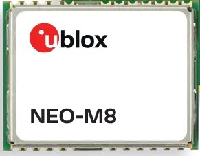
The NEO-M8N is a high-performance GPS module manufactured by U-Blox (Part ID: NEO-M8N-0-12). It is designed to provide accurate and reliable positioning data by supporting multiple Global Navigation Satellite Systems (GNSS), including GPS, GLONASS, Galileo, and BeiDou. The module is known for its fast time-to-first-fix (TTFF), low power consumption, and robust performance, making it suitable for a wide range of applications.
Explore Projects Built with NEO-M8N

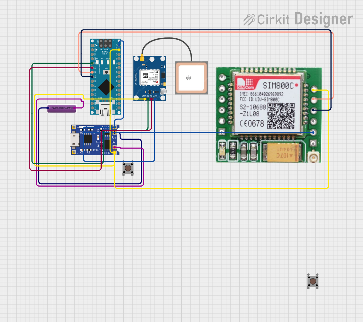
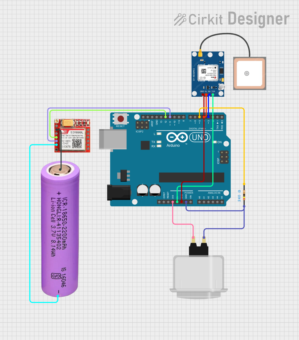

Explore Projects Built with NEO-M8N
Common Applications and Use Cases
- Drones and UAVs: For precise navigation and positioning.
- Robotics: To enable autonomous movement and location tracking.
- Automotive Navigation: For real-time vehicle tracking and route optimization.
- Geographic Information Systems (GIS): For mapping and surveying.
- IoT Devices: To provide location-based services in smart devices.
Technical Specifications
The NEO-M8N module is packed with advanced features and specifications to meet the demands of modern GNSS applications.
Key Technical Details
| Parameter | Specification |
|---|---|
| GNSS Support | GPS, GLONASS, Galileo, BeiDou |
| Frequency Bands | L1 (1575.42 MHz) |
| Position Accuracy | 2.5 m CEP (Circular Error Probable) |
| Time-to-First-Fix (TTFF) | Cold Start: 26 s, Hot Start: 1 s |
| Update Rate | Up to 10 Hz |
| Operating Voltage | 2.7 V to 3.6 V |
| Power Consumption | ~23 mA @ 3.0 V (continuous tracking) |
| Communication Interfaces | UART, I2C, SPI |
| Operating Temperature | -40°C to +85°C |
| Dimensions | 12.2 mm x 16.0 mm x 2.4 mm |
Pin Configuration and Descriptions
The NEO-M8N module has a standard pinout for easy integration into circuits. Below is the pin configuration:
| Pin Number | Pin Name | Description |
|---|---|---|
| 1 | VCC | Power supply input (2.7 V to 3.6 V) |
| 2 | GND | Ground connection |
| 3 | TXD | UART Transmit Data |
| 4 | RXD | UART Receive Data |
| 5 | SDA | I2C Data Line |
| 6 | SCL | I2C Clock Line |
| 7 | PPS | Pulse Per Second output for timing applications |
| 8 | RESET_N | Active-low reset input |
Usage Instructions
The NEO-M8N module is versatile and can be used in various circuits. Below are the steps and best practices for using the module effectively.
How to Use the NEO-M8N in a Circuit
- Power Supply: Connect the VCC pin to a regulated 3.3 V power source and the GND pin to ground.
- Communication Interface: Choose a communication protocol (UART, I2C, or SPI) based on your application:
- For UART, connect the TXD and RXD pins to the corresponding UART pins of your microcontroller.
- For I2C, connect the SDA and SCL pins to the I2C bus.
- Antenna Connection: Attach an active GPS antenna to the module's antenna connector for optimal signal reception.
- Pulse Per Second (PPS): Use the PPS pin for precise timing applications if required.
- Reset: Optionally, connect the RESET_N pin to a microcontroller GPIO for manual reset functionality.
Important Considerations and Best Practices
- Antenna Placement: Ensure the GPS antenna has a clear view of the sky for optimal satellite reception.
- Power Supply: Use a stable and noise-free power source to avoid interference with GNSS signals.
- Baud Rate: Configure the UART baud rate to match the default or desired setting (typically 9600 bps).
- Firmware Updates: Check for firmware updates from U-Blox to ensure the module operates with the latest features and fixes.
Example: Connecting NEO-M8N to Arduino UNO
Below is an example of how to connect the NEO-M8N module to an Arduino UNO using UART and read GPS data.
Wiring Diagram
| NEO-M8N Pin | Arduino UNO Pin |
|---|---|
| VCC | 3.3 V |
| GND | GND |
| TXD | RX (Pin 0) |
| RXD | TX (Pin 1) |
Arduino Code
#include <SoftwareSerial.h>

// Define RX and TX pins for SoftwareSerial
SoftwareSerial gpsSerial(4, 3); // RX = Pin 4, TX = Pin 3

void setup() {
  Serial.begin(9600); // Initialize Serial Monitor
  gpsSerial.begin(9600); // Initialize GPS module communication

  Serial.println("NEO-M8N GPS Module Test");
}

void loop() {
  // Check if data is available from the GPS module
  while (gpsSerial.available()) {
    char c = gpsSerial.read(); // Read one character from GPS
    Serial.print(c); // Print the character to Serial Monitor
  }
}
Notes
- Use SoftwareSerial if the Arduino's hardware UART is already in use.
- Ensure the GPS antenna is connected and has a clear view of the sky for accurate data.
Troubleshooting and FAQs
Common Issues and Solutions
No GPS Fix:
- Cause: Poor antenna placement or obstructed view of the sky.
- Solution: Place the antenna in an open area with a clear view of the sky.
No Data Output:
- Cause: Incorrect wiring or baud rate mismatch.
- Solution: Verify connections and ensure the baud rate matches the module's configuration.
Intermittent Signal Loss:
- Cause: Power supply noise or interference.
- Solution: Use a stable power source and shield the module from nearby electronic noise.
Module Not Responding:
- Cause: Module not powered or reset incorrectly.
- Solution: Check the power supply and ensure the RESET_N pin is not held low.
FAQs
Q: Can the NEO-M8N operate indoors?
A: While the module can operate indoors, signal reception may be weak or unavailable due to obstructions.Q: What is the maximum update rate of the NEO-M8N?
A: The module supports an update rate of up to 10 Hz.Q: Does the NEO-M8N support SBAS (Satellite-Based Augmentation Systems)?
A: Yes, the module supports SBAS for improved accuracy.Q: Can I use the NEO-M8N with a 5V microcontroller?
A: Yes, but you must use a level shifter to convert 5V signals to 3.3V to avoid damaging the module.
By following this documentation, users can effectively integrate and utilize the NEO-M8N GPS module in their projects.