
How to Use Adafruit FONA 808 Breakout: Examples, Pinouts, and Specs
 Design with Adafruit FONA 808 Breakout in Cirkit Designer
Introduction
The Adafruit FONA 808 Breakout (Manufacturer Part ID: 2542) is a compact GSM/GPRS module designed for cellular communication in embedded systems. It integrates a SIM808 chipset, which combines GSM/GPRS functionality with GPS capabilities, making it ideal for projects requiring both communication and location tracking. This module supports SMS, voice calls, and data transfer over 2G networks, as well as GPS for navigation and tracking.
Explore Projects Built with Adafruit FONA 808 Breakout
 Open Project in Cirkit Designer
 Open Project in Cirkit Designer
 Open Project in Cirkit Designer
 Open Project in Cirkit Designer
Explore Projects Built with Adafruit FONA 808 Breakout
Open Project in Cirkit DesignerOpen Project in Cirkit DesignerOpen Project in Cirkit DesignerOpen Project in Cirkit DesignerCommon Applications and Use Cases
- IoT (Internet of Things) devices requiring cellular connectivity
- GPS tracking systems for vehicles or personal devices
- Remote monitoring and control systems
- SMS-based alert systems
- Embedded projects requiring voice call functionality
Technical Specifications
The Adafruit FONA 808 Breakout is a feature-rich module with the following key specifications:
| Specification | Details |
|---|---|
| Chipset | SIM808 (GSM/GPRS + GPS) |
| Operating Voltage | 3.3V to 4.4V (recommended: 3.7V LiPo battery) |
| Current Consumption | Idle: ~20mA, GSM active: ~200mA, Peak: ~2A |
| Frequency Bands | Quad-band: 850/900/1800/1900 MHz |
| GPS Sensitivity | -165 dBm |
| GPS Cold Start Time | ~30 seconds |
| GPS Hot Start Time | ~1 second |
| Data Transfer | GPRS Class 12, up to 85.6 kbps |
| SIM Card Support | Micro SIM |
| Audio Support | Microphone and speaker interface for voice calls |
| Dimensions | 1.75" x 1.25" x 0.25" (44.5mm x 31.75mm x 6.5mm) |
Pin Configuration and Descriptions
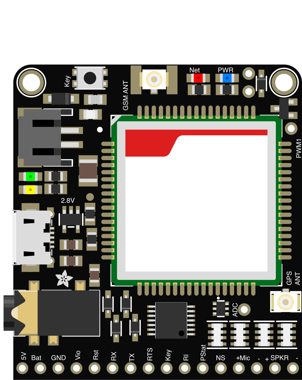
The Adafruit FONA 808 Breakout has a variety of pins for power, communication, and peripheral connections. Below is the pinout:
| Pin Name | Type | Description |
|---|---|---|
| VIN | Power Input | Main power input (3.3V to 4.4V). Use a 3.7V LiPo battery for best performance. |
| GND | Ground | Ground connection. |
| VIO | Power Input | Logic level voltage (1.8V to 5V). |
| TX | Output | UART Transmit pin (connect to RX of microcontroller). |
| RX | Input | UART Receive pin (connect to TX of microcontroller). |
| RST | Input | Reset pin (active low). |
| KEY | Input | Power on/off control pin (active low). |
| MIC+ / MIC- | Audio Input | Microphone positive and negative terminals. |
| SPK+ / SPK- | Audio Output | Speaker positive and negative terminals. |
| NET | Status Output | Network status LED pin (blinks to indicate GSM activity). |
| GPS_TX | Output | GPS UART Transmit pin. |
| GPS_RX | Input | GPS UART Receive pin. |
Usage Instructions
How to Use the Component in a Circuit
- Power Supply: Connect a 3.7V LiPo battery to the VIN and GND pins. Ensure the battery can supply up to 2A for GSM peak current.
- Logic Level: Connect the VIO pin to the logic level voltage of your microcontroller (e.g., 3.3V or 5V).
- UART Communication: Connect the TX and RX pins to the corresponding RX and TX pins of your microcontroller.
- Antenna: Attach the GSM and GPS antennas to the respective connectors on the module.
- SIM Card: Insert a micro SIM card into the SIM card slot.
- Power On: Pull the KEY pin low for at least 2 seconds to power on the module.
Important Considerations and Best Practices
- Use a capacitor (e.g., 1000 µF) across the power supply to handle GSM peak current.
- Ensure the GSM and GPS antennas are securely connected for reliable operation.
- Place the module in an area with good cellular and GPS signal reception.
- Avoid placing the module near high-frequency noise sources to prevent interference.
Example: Connecting to an Arduino UNO
Below is an example of how to use the Adafruit FONA 808 Breakout with an Arduino UNO to send an SMS:
Circuit Connections
| FONA Pin | Arduino Pin |
|---|---|
| VIO | 5V |
| GND | GND |
| TX | D2 (Software RX) |
| RX | D3 (Software TX) |
| KEY | GND (momentary) |
Arduino Code
#include <SoftwareSerial.h>

// Define FONA pins
#define FONA_RX 2  // FONA TX pin connected to Arduino D2
#define FONA_TX 3  // FONA RX pin connected to Arduino D3

// Create a SoftwareSerial object for FONA communication
SoftwareSerial fonaSerial(FONA_RX, FONA_TX);

void setup() {
  // Initialize serial communication
  Serial.begin(9600);  // For debugging
  fonaSerial.begin(4800);  // FONA baud rate

  Serial.println("Initializing FONA...");

  // Send AT command to check communication
  fonaSerial.println("AT");
  delay(1000);

  // Check for response
  if (fonaSerial.available()) {
    Serial.println("FONA is ready!");
  } else {
    Serial.println("No response from FONA. Check connections.");
  }

  // Send SMS
  sendSMS("+1234567890", "Hello from FONA 808!");
}

void loop() {
  // Nothing to do in the loop
}

// Function to send an SMS
void sendSMS(const char* phoneNumber, const char* message) {
  fonaSerial.println("AT+CMGF=1");  // Set SMS mode to text
  delay(1000);

  fonaSerial.print("AT+CMGS=\"");
  fonaSerial.print(phoneNumber);
  fonaSerial.println("\"");
  delay(1000);

  fonaSerial.print(message);  // Send the message
  delay(1000);

  fonaSerial.write(26);  // Send Ctrl+Z to indicate end of message
  delay(5000);

  Serial.println("SMS sent!");
}
Troubleshooting and FAQs
Common Issues and Solutions
No Response from the Module:
- Ensure the module is powered on (KEY pin pulled low for 2 seconds).
- Check the power supply and ensure it can handle peak current (~2A).
- Verify UART connections (TX to RX and RX to TX).
GSM Network Not Detected:
- Confirm the SIM card is inserted correctly and is active.
- Check the GSM antenna connection.
- Ensure the module is in an area with good cellular signal.
GPS Not Working:
- Verify the GPS antenna is connected securely.
- Place the module in an open area with a clear view of the sky.
SMS Not Sending:
- Ensure the SIM card has sufficient balance or SMS plan.
- Verify the phone number format (e.g., include country code).
FAQs
Q: Can the FONA 808 work with 3G or 4G networks?
A: No, the FONA 808 supports only 2G GSM networks. Ensure your carrier supports 2G.
Q: What is the maximum baud rate for UART communication?
A: The SIM808 supports baud rates up to 115200 bps.
Q: Can I use the GPS and GSM functions simultaneously?
A: Yes, the SIM808 allows concurrent use of GSM and GPS functionalities.
Q: How do I reset the module?
A: Pull the RST pin low for at least 100 ms to reset the module.