How to Use Датчик розбиття скла: Examples, Pinouts, and Specs
Introduction
- The Датчик розбиття скла (Glass Break Sensor) is an electronic component designed to detect the sound or vibration caused by breaking glass. It is commonly used in security systems to provide an early warning of potential intrusions.
- Typical applications include home and office security systems, smart home automation, and industrial safety systems. The sensor can trigger alarms, send notifications, or activate other security measures when glass breakage is detected.
Explore Projects Built with Датчик розбиття скла


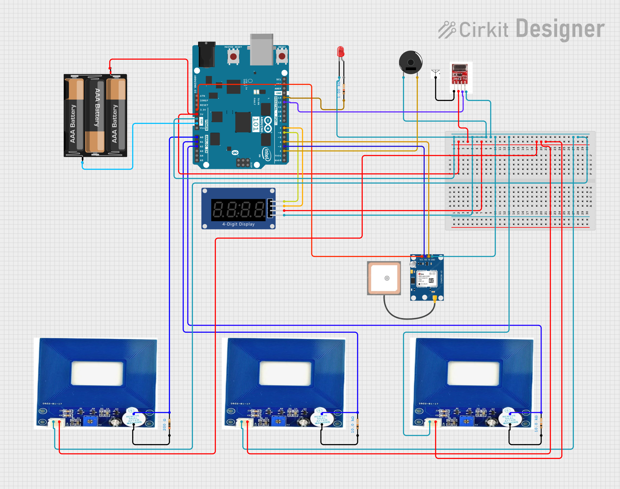
Explore Projects Built with Датчик розбиття скла
Technical Specifications
- Detection Method: Acoustic or vibration-based
- Operating Voltage: 3.3V to 5V DC
- Current Consumption: < 20mA
- Output Type: Digital (High/Low signal)
- Detection Range: Up to 6 meters (depending on the environment)
- Operating Temperature: -10°C to 50°C
- Dimensions: Varies by model, typically compact for easy integration
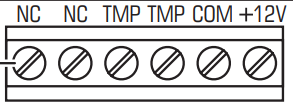
Pin Configuration and Descriptions
| Pin | Name | Description |
|---|---|---|
| 1 | VCC | Power supply input (3.3V to 5V DC) |
| 2 | GND | Ground connection |
| 3 | OUT | Digital output signal (High when glass break is detected, Low otherwise) |
| 4 | ADJ (optional) | Sensitivity adjustment pin (if available, used to fine-tune detection threshold) |
Usage Instructions
Connecting the Sensor:
- Connect the VCC pin to a 3.3V or 5V power source.
- Connect the GND pin to the ground of your circuit.
- Connect the OUT pin to a digital input pin on your microcontroller or alarm system.
- If the sensor has an ADJ pin, use a potentiometer or resistor to adjust the sensitivity as needed.
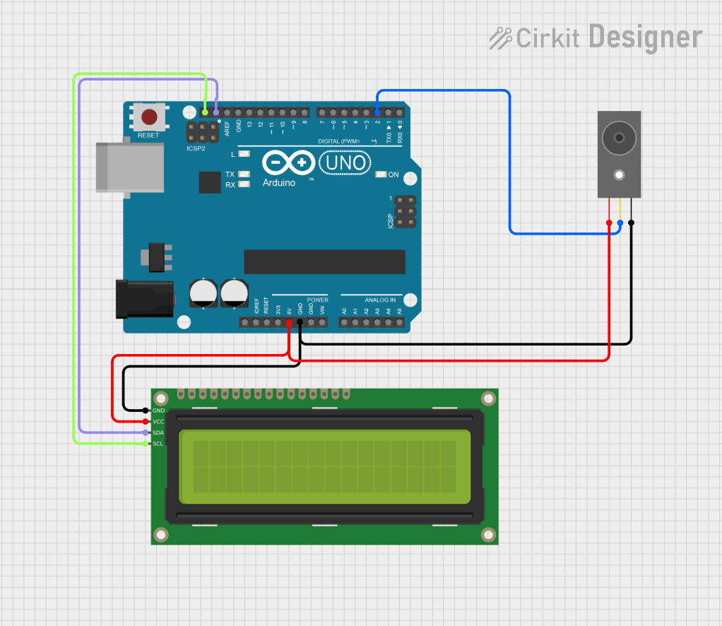
Integrating with an Arduino UNO:
- The sensor can be easily connected to an Arduino UNO for testing or integration into a larger system. Below is an example code snippet:
// Glass Break Sensor Example with Arduino UNO
// This code reads the sensor's output and triggers an alert when glass break is detected.

const int sensorPin = 2;  // Connect the OUT pin of the sensor to digital pin 2
const int ledPin = 13;    // Built-in LED on Arduino for visual alert

void setup() {
  pinMode(sensorPin, INPUT);  // Set sensor pin as input
  pinMode(ledPin, OUTPUT);    // Set LED pin as output
  Serial.begin(9600);         // Initialize serial communication for debugging
}

void loop() {
  int sensorValue = digitalRead(sensorPin);  // Read the sensor's output

  if (sensorValue == HIGH) {
    // Glass break detected
    digitalWrite(ledPin, HIGH);  // Turn on the LED
    Serial.println("Glass break detected!"); // Print alert to serial monitor
    delay(1000);  // Wait for 1 second to avoid multiple triggers
  } else {
    // No glass break detected
    digitalWrite(ledPin, LOW);  // Turn off the LED
  }
}
- Important Considerations:
- Ensure the sensor is placed in a location where it can clearly detect the sound or vibration of breaking glass.
- Avoid placing the sensor near sources of loud, continuous noise, as this may cause false triggers.
- Test the sensor in the intended environment to ensure proper sensitivity and detection range.
Troubleshooting and FAQs
Common Issues
The sensor does not detect glass breakage.
- Solution: Check the power supply connections and ensure the sensor is receiving the correct voltage.
- Solution: Adjust the sensitivity using the ADJ pin (if available) to better suit the environment.
False triggers occur frequently.
- Solution: Relocate the sensor away from sources of loud, continuous noise or vibrations.
- Solution: Reduce the sensitivity using the ADJ pin or by adding a resistor.
No output signal is received.
- Solution: Verify the connection between the sensor's OUT pin and the microcontroller or alarm system.
- Solution: Test the sensor with a multimeter to ensure it is functioning correctly.
FAQs
Q: Can this sensor detect other types of sounds?
A: No, the sensor is specifically designed to detect the unique sound or vibration pattern of breaking glass.Q: How do I test the sensor without breaking actual glass?
A: You can use a recording of breaking glass played at a sufficient volume near the sensor to simulate the sound.Q: Can I use this sensor outdoors?
A: The sensor is typically designed for indoor use. If used outdoors, ensure it is protected from moisture and extreme temperatures.Q: What is the maximum detection range?
A: The sensor can detect glass breakage up to 6 meters away, depending on environmental factors such as noise and obstructions.