
How to Use Adafruit Mini 8x8 LED Matrix Backpack - White: Examples, Pinouts, and Specs
 Design with Adafruit Mini 8x8 LED Matrix Backpack - White in Cirkit Designer
Introduction
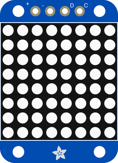
The Adafruit Mini 8x8 LED Matrix Backpack - White (Manufacturer Part ID: 1080) is a compact and versatile LED display module featuring an 8x8 grid of white LEDs. This module is designed for easy integration into projects requiring simple graphics, animations, or text displays. It uses the I2C communication protocol, which minimizes the number of pins required for connection to a microcontroller, such as an Arduino.
Explore Projects Built with Adafruit Mini 8x8 LED Matrix Backpack - White
 Open Project in Cirkit Designer
 Open Project in Cirkit Designer
 Open Project in Cirkit Designer
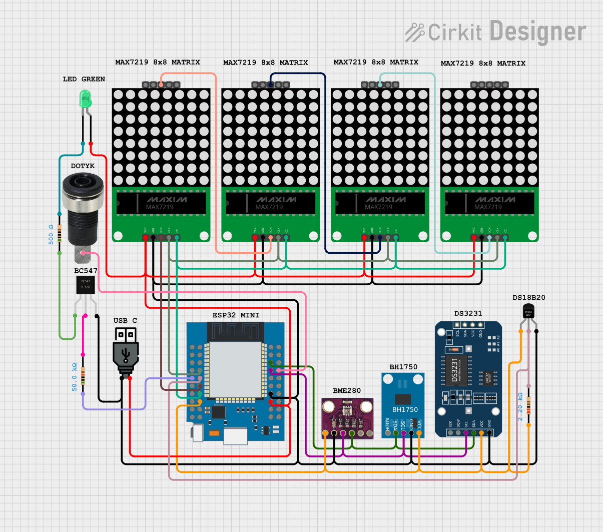 Open Project in Cirkit Designer
Explore Projects Built with Adafruit Mini 8x8 LED Matrix Backpack - White
Open Project in Cirkit DesignerOpen Project in Cirkit DesignerOpen Project in Cirkit DesignerOpen Project in Cirkit DesignerCommon Applications
- Displaying scrolling text or simple animations
- Visual indicators for IoT devices
- Status displays for embedded systems
- Educational projects and prototyping
Technical Specifications
The following table outlines the key technical details of the Adafruit Mini 8x8 LED Matrix Backpack:
| Specification | Details |
|---|---|
| Manufacturer | Adafruit |
| Manufacturer Part ID | 1080 |
| LED Matrix Dimensions | 8x8 grid (64 LEDs total) |
| LED Color | White |
| Communication Protocol | I2C |
| Operating Voltage | 5V DC |
| Current Consumption | ~20mA (typical, varies with usage) |
| Dimensions | 27mm x 27mm x 4mm (excluding pins) |
| Weight | 4g |
Pin Configuration
The module has a simple 4-pin interface for I2C communication. The pinout is as follows:
| Pin | Label | Description |
|---|---|---|
| 1 | GND | Ground connection |
| 2 | VCC | Power supply (5V DC) |
| 3 | SDA | I2C data line |
| 4 | SCL | I2C clock line |
Usage Instructions
Connecting the Module
To use the Adafruit Mini 8x8 LED Matrix Backpack with an Arduino UNO, follow these steps:
- Wiring: Connect the module to the Arduino as shown below:
- GND → GND
- VCC → 5V
- SDA → A4 (on Arduino UNO)
- SCL → A5 (on Arduino UNO)
- Install Libraries: Download and install the Adafruit GFX and Adafruit LED Backpack libraries from the Arduino Library Manager.
- Upload Code: Use the example code below to display text or graphics.
Example Code
The following Arduino sketch demonstrates how to display scrolling text on the LED matrix:
#include <Wire.h>
#include <Adafruit_GFX.h>
#include <Adafruit_LEDBackpack.h>

// Create an instance of the LED matrix
Adafruit_8x8matrix matrix = Adafruit_8x8matrix();

void setup() {
  // Initialize the LED matrix
  matrix.begin(0x70); // Default I2C address is 0x70
  matrix.clear();
  matrix.writeDisplay();
}

void loop() {
  // Display scrolling text
  static const uint8_t text[] = "HELLO ";
  for (int i = 0; i < sizeof(text) - 1; i++) {
    matrix.clear();
    matrix.drawChar(0, 0, text[i], LED_ON, LED_OFF, 1);
    matrix.writeDisplay();
    delay(500); // Pause for half a second
  }
}
Best Practices
- Ensure proper power supply (5V DC) to avoid damaging the module.
- Use pull-up resistors on the SDA and SCL lines if your microcontroller does not have internal pull-ups enabled.
- Avoid excessive current draw by limiting the number of LEDs lit simultaneously.
Troubleshooting and FAQs
Common Issues
No Display Output:
- Verify all connections (GND, VCC, SDA, SCL) are secure.
- Ensure the correct I2C address (default: 0x70) is used in the code.
- Check if the Adafruit GFX and LED Backpack libraries are installed correctly.
Flickering or Dim LEDs:
- Ensure the power supply provides sufficient current (at least 20mA).
- Check for loose or poor-quality wiring.
I2C Communication Errors:
- Confirm that the SDA and SCL pins are connected to the correct pins on the microcontroller.
- Use a logic analyzer or I2C scanner sketch to verify the module's I2C address.
FAQs
Q: Can I change the I2C address of the module?
A: Yes, the module supports address configuration via solder jumpers on the back. Refer to the Adafruit guide for details.
Q: Can I use this module with a 3.3V microcontroller?
A: Yes, but you must ensure the I2C lines are properly level-shifted to avoid damaging the module.
Q: How many modules can I chain together?
A: Up to 8 modules can be chained by assigning unique I2C addresses to each.
By following this documentation, you can effectively integrate the Adafruit Mini 8x8 LED Matrix Backpack into your projects for dynamic and engaging displays.