How to Use L298N Motor Driver Board Module: Examples, Pinouts, and Specs
Introduction
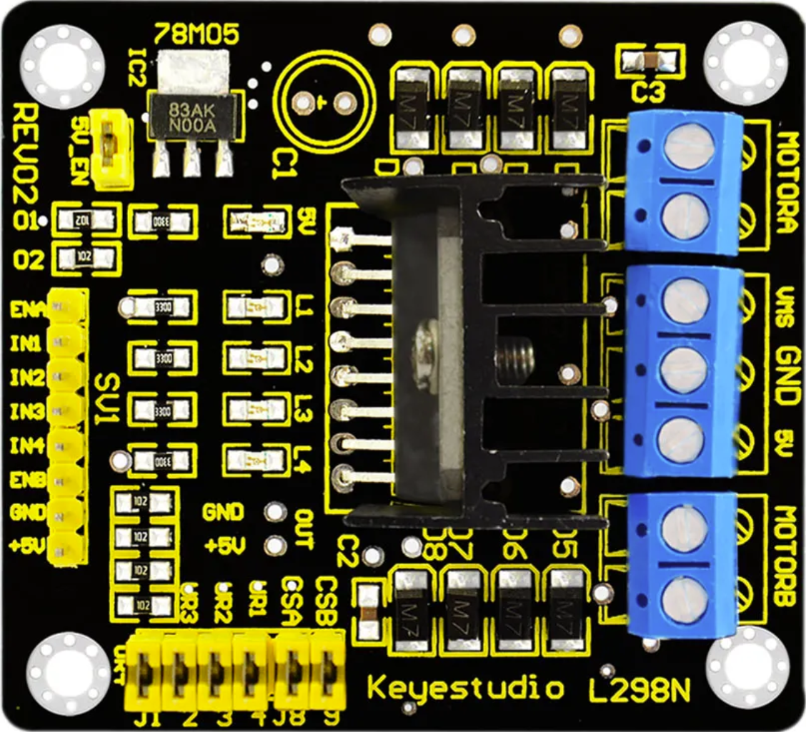
The L298N Motor Driver Board Module (Manufacturer: Keyestudio, Part ID: Ks0063) is a dual H-bridge motor driver designed to control the direction and speed of DC motors and stepper motors. It is capable of driving two motors simultaneously, making it an essential component in robotics, automation, and motor control projects. The module is widely used due to its simplicity, reliability, and ability to handle high current loads.
Explore Projects Built with L298N Motor Driver Board Module
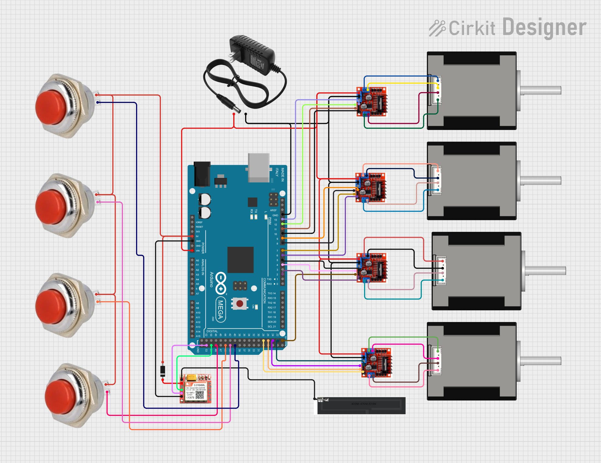

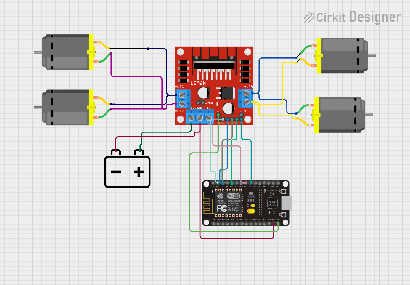
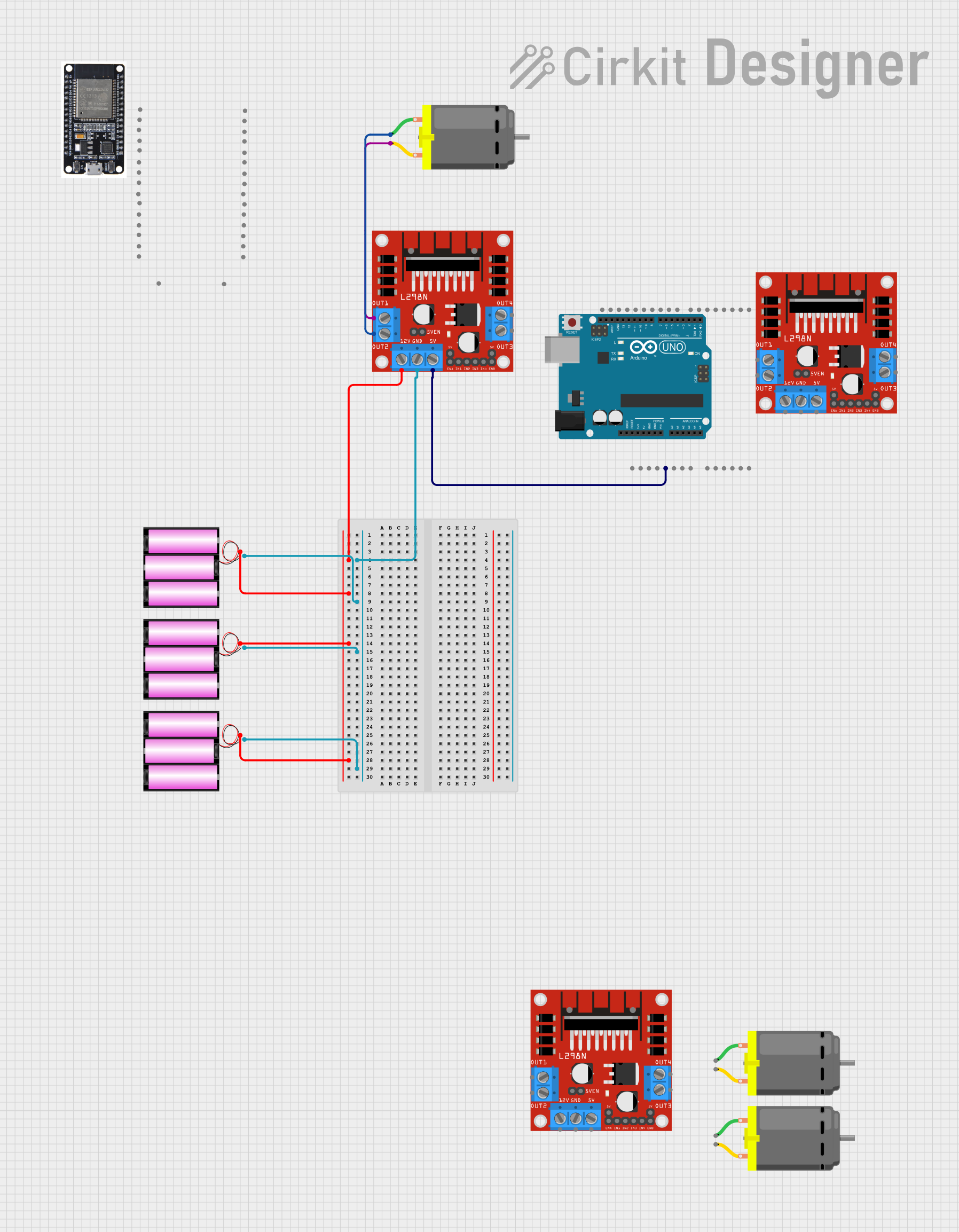
Explore Projects Built with L298N Motor Driver Board Module
Common Applications
- Robotics (e.g., controlling robot wheels)
- Automation systems
- Conveyor belts
- DIY motorized projects
- Stepper motor control for CNC machines or 3D printers
Technical Specifications
The following are the key technical details of the L298N Motor Driver Board Module:
| Parameter | Specification |
|---|---|
| Operating Voltage | 5V to 35V |
| Logic Voltage | 5V |
| Maximum Output Current | 2A per channel (continuous) |
| Peak Output Current | 3A per channel (short duration) |
| Power Dissipation | 25W (with proper heat dissipation) |
| Control Logic Levels | High: 2.3V to 5V, Low: 0V |
| Motor Channels | 2 (dual H-bridge) |
| Dimensions | 43mm x 43mm x 27mm |
| Weight | ~30g |
Pin Configuration and Descriptions
The L298N module has several pins and terminals for motor control and power input. Below is a detailed description:
Power and Motor Terminals
| Pin/Terminal | Description |
|---|---|
VCC |
Power supply for motors (5V to 35V). |
GND |
Ground connection. |
5V |
5V output (used to power logic circuits if needed). |
OUT1 |
Output for Motor 1 (connect to one motor terminal). |
OUT2 |
Output for Motor 1 (connect to the other motor terminal). |
OUT3 |
Output for Motor 2 (connect to one motor terminal). |
OUT4 |
Output for Motor 2 (connect to the other motor terminal). |
Control Pins
| Pin | Description |
|---|---|
ENA |
Enable pin for Motor 1 (PWM input for speed control). |
ENB |
Enable pin for Motor 2 (PWM input for speed control). |
IN1 |
Control input for Motor 1 (direction control). |
IN2 |
Control input for Motor 1 (direction control). |
IN3 |
Control input for Motor 2 (direction control). |
IN4 |
Control input for Motor 2 (direction control). |
Usage Instructions
How to Use the L298N in a Circuit
- Power the Module: Connect the
VCCterminal to a power source (5V to 35V) and theGNDterminal to ground. If your motor voltage is 12V, connect a 12V power supply toVCC. - Connect Motors: Attach the motor terminals to
OUT1andOUT2for Motor 1, andOUT3andOUT4for Motor 2. - Control Pins: Use the
IN1,IN2,IN3, andIN4pins to control the direction of the motors. Apply a HIGH or LOW signal to these pins based on the desired direction. - Speed Control: Use the
ENAandENBpins to control the speed of the motors by providing a PWM signal.
Important Considerations
- Heat Dissipation: The L298N module can get hot during operation. Use the onboard heat sink or an external cooling fan for high-current applications.
- Power Supply: Ensure the power supply voltage matches the motor's requirements. Do not exceed the module's maximum voltage rating of 35V.
- Logic Voltage: The control pins operate at 5V logic levels. If using a 3.3V microcontroller, use a level shifter to avoid damage.
Example: Connecting to an Arduino UNO
Below is an example of how to control a DC motor using the L298N module and an Arduino UNO:
Circuit Connections
- Connect
VCCto a 12V power supply andGNDto ground. - Connect
OUT1andOUT2to the terminals of the DC motor. - Connect
ENAto Arduino pin 9 (PWM output). - Connect
IN1to Arduino pin 8 andIN2to Arduino pin 7.
Arduino Code
// Define control pins for Motor 1
#define ENA 9  // PWM pin for speed control
#define IN1 8  // Direction control pin 1
#define IN2 7  // Direction control pin 2

void setup() {
  // Set motor control pins as outputs
  pinMode(ENA, OUTPUT);
  pinMode(IN1, OUTPUT);
  pinMode(IN2, OUTPUT);
}

void loop() {
  // Rotate motor in one direction
  digitalWrite(IN1, HIGH);  // Set IN1 HIGH
  digitalWrite(IN2, LOW);   // Set IN2 LOW
  analogWrite(ENA, 150);    // Set speed (0-255)

  delay(2000);              // Run for 2 seconds

  // Stop the motor
  digitalWrite(ENA, LOW);   // Disable motor
  delay(1000);              // Wait for 1 second

  // Rotate motor in the opposite direction
  digitalWrite(IN1, LOW);   // Set IN1 LOW
  digitalWrite(IN2, HIGH);  // Set IN2 HIGH
  analogWrite(ENA, 200);    // Set speed (0-255)

  delay(2000);              // Run for 2 seconds

  // Stop the motor
  digitalWrite(ENA, LOW);   // Disable motor
  delay(1000);              // Wait for 1 second
}
Troubleshooting and FAQs
Common Issues
Motor Not Spinning:
- Check the power supply voltage and ensure it matches the motor's requirements.
- Verify the connections to the motor terminals (
OUT1,OUT2, etc.). - Ensure the control pins (
IN1,IN2, etc.) are receiving the correct HIGH/LOW signals.
Overheating:
- The module may overheat if the current exceeds 2A per channel. Use a cooling fan or reduce the load.
No Response from Motors:
- Ensure the
ENAandENBpins are enabled (PWM signal or HIGH). - Check for loose connections or damaged wires.
- Ensure the
FAQs
Q: Can I use the L298N with a 3.3V microcontroller?
A: Yes, but you will need a level shifter to convert the 3.3V logic signals to 5V.
Q: Can the L298N drive stepper motors?
A: Yes, the L298N can control stepper motors by using both H-bridge channels. Refer to the stepper motor's datasheet for wiring details.
Q: What is the maximum motor voltage supported?
A: The module supports motor voltages up to 35V. Ensure your power supply does not exceed this limit.