Cirkit Designer Logo
Cirkit Designer
Your all-in-one circuit design IDE
Home / 
Component Documentation

How to Use QMC5883L: Examples, Pinouts, and Specs

Image of QMC5883L
Cirkit Designer LogoDesign with QMC5883L in Cirkit Designer

Introduction

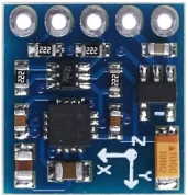
The QMC5883L, manufactured by QST, is a digital compass sensor designed to measure magnetic fields in three dimensions (X, Y, and Z axes). It provides precise heading information, making it an essential component in navigation systems, robotics, and mobile devices. With its compact size and I2C interface, the QMC5883L is easy to integrate into a wide range of applications.

Explore Projects Built with QMC5883L

Use Cirkit Designer to design, explore, and prototype these projects online. Some projects support real-time simulation. Click "Open Project" to start designing instantly!
Cellular-Enabled IoT Device with Real-Time Clock and Power Management
Image of LRCM PHASE 2 BASIC: A project utilizing QMC5883L in a practical application
This circuit features a LilyGo-SIM7000G module for cellular communication and GPS functionality, interfaced with an RTC DS3231 for real-time clock capabilities. It includes voltage sensing through two voltage sensor modules, and uses an 8-channel opto-coupler for isolating different parts of the circuit. Power management is handled by a buck converter connected to a DC power source and batteries, with a fuse for protection and a rocker switch for on/off control. Additionally, there's an LED for indication purposes.
Cirkit Designer LogoOpen Project in Cirkit Designer
Battery-Powered Health Monitoring System with Nucleo WB55RG and OLED Display
Image of Pulsefex: A project utilizing QMC5883L in a practical application
This circuit is a multi-sensor data acquisition system that uses a Nucleo WB55RG microcontroller to interface with a digital temperature sensor (TMP102), a pulse oximeter and heart-rate sensor (MAX30102), and a 0.96" OLED display via I2C. Additionally, it includes a Sim800l module for GSM communication, powered by a 3.7V LiPo battery.
Cirkit Designer LogoOpen Project in Cirkit Designer
Arduino Nano Based GPS Tracker with GSM Communication and Accelerometer
Image of Circuit Aayush: A project utilizing QMC5883L in a practical application
This circuit is designed for communication and location tracking purposes. It features an Arduino Nano interfaced with a SIM800L GSM module for cellular connectivity, a GPS NEO 6M module for obtaining geographical coordinates, and an AITrip ADXL335 GY-61 accelerometer for motion sensing. The LM2596 Step Down Module is used to regulate the power supply to the components.
Cirkit Designer LogoOpen Project in Cirkit Designer
Raspberry Pi Pico-Based Navigation Assistant with Bluetooth and GPS
Image of sat_dish: compass example: A project utilizing QMC5883L in a practical application
This circuit features a Raspberry Pi Pico microcontroller interfaced with an HC-05 Bluetooth module for wireless communication, an HMC5883L compass module for magnetic field measurement, and a GPS NEO 6M module for location tracking. The Pico is configured to communicate with the HC-05 via serial connection (TX/RX), with the compass module via I2C (SCL/SDA), and with the GPS module via serial (TX/RX). Common power (VCC) and ground (GND) lines are shared among all modules, indicating a unified power system.
Cirkit Designer LogoOpen Project in Cirkit Designer

Explore Projects Built with QMC5883L

Use Cirkit Designer to design, explore, and prototype these projects online. Some projects support real-time simulation. Click "Open Project" to start designing instantly!
Image of LRCM PHASE 2 BASIC: A project utilizing QMC5883L in a practical application
Cellular-Enabled IoT Device with Real-Time Clock and Power Management
This circuit features a LilyGo-SIM7000G module for cellular communication and GPS functionality, interfaced with an RTC DS3231 for real-time clock capabilities. It includes voltage sensing through two voltage sensor modules, and uses an 8-channel opto-coupler for isolating different parts of the circuit. Power management is handled by a buck converter connected to a DC power source and batteries, with a fuse for protection and a rocker switch for on/off control. Additionally, there's an LED for indication purposes.
Cirkit Designer LogoOpen Project in Cirkit Designer
Image of Pulsefex: A project utilizing QMC5883L in a practical application
Battery-Powered Health Monitoring System with Nucleo WB55RG and OLED Display
This circuit is a multi-sensor data acquisition system that uses a Nucleo WB55RG microcontroller to interface with a digital temperature sensor (TMP102), a pulse oximeter and heart-rate sensor (MAX30102), and a 0.96" OLED display via I2C. Additionally, it includes a Sim800l module for GSM communication, powered by a 3.7V LiPo battery.
Cirkit Designer LogoOpen Project in Cirkit Designer
Image of Circuit Aayush: A project utilizing QMC5883L in a practical application
Arduino Nano Based GPS Tracker with GSM Communication and Accelerometer
This circuit is designed for communication and location tracking purposes. It features an Arduino Nano interfaced with a SIM800L GSM module for cellular connectivity, a GPS NEO 6M module for obtaining geographical coordinates, and an AITrip ADXL335 GY-61 accelerometer for motion sensing. The LM2596 Step Down Module is used to regulate the power supply to the components.
Cirkit Designer LogoOpen Project in Cirkit Designer
Image of sat_dish: compass example: A project utilizing QMC5883L in a practical application
Raspberry Pi Pico-Based Navigation Assistant with Bluetooth and GPS
This circuit features a Raspberry Pi Pico microcontroller interfaced with an HC-05 Bluetooth module for wireless communication, an HMC5883L compass module for magnetic field measurement, and a GPS NEO 6M module for location tracking. The Pico is configured to communicate with the HC-05 via serial connection (TX/RX), with the compass module via I2C (SCL/SDA), and with the GPS module via serial (TX/RX). Common power (VCC) and ground (GND) lines are shared among all modules, indicating a unified power system.
Cirkit Designer LogoOpen Project in Cirkit Designer

Common Applications and Use Cases

  • Navigation systems (e.g., GPS modules with heading correction)
  • Robotics for orientation and pathfinding
  • Mobile devices for augmented reality and compass functionality
  • Drones for stabilization and direction control
  • Scientific instruments for magnetic field measurement

Technical Specifications

The QMC5883L is a high-performance magnetometer with the following key specifications:

Parameter Value
Manufacturer QST
Part ID QMC5883L
Operating Voltage 2.16V to 3.6V
Interface I2C
Measurement Range ±8 Gauss
Resolution 12-bit
Output Data Rate (ODR) 10Hz, 50Hz, 100Hz, 200Hz
Operating Temperature -40°C to +85°C
Power Consumption 100 µA (typical)
Dimensions 3mm x 3mm x 0.9mm

Pin Configuration and Descriptions

The QMC5883L has a total of 8 pins, but only 4 are typically used for operation. Below is the pin configuration:

Pin Name Pin Number Description
VDD 1 Power supply (2.16V to 3.6V)
GND 2 Ground
SDA 3 I2C data line
SCL 4 I2C clock line
DRDY 5 Data ready signal (optional)
NC 6, 7, 8 Not connected (leave unconnected)

Usage Instructions

How to Use the QMC5883L in a Circuit

  1. Power Supply: Connect the VDD pin to a 3.3V power source and the GND pin to ground.
  2. I2C Communication: Connect the SDA and SCL pins to the corresponding I2C pins on your microcontroller. Use pull-up resistors (typically 4.7kΩ) on both SDA and SCL lines if not already present on your board.
  3. Optional DRDY Pin: The DRDY pin can be used to detect when new data is available. If not used, leave it unconnected.
  4. Address: The default I2C address of the QMC5883L is 0x0D.

Important Considerations and Best Practices

  • Magnetic Interference: Avoid placing the QMC5883L near ferromagnetic materials or strong magnetic fields, as they can distort measurements.
  • Calibration: Perform a calibration routine to account for hard-iron and soft-iron distortions in your environment.
  • Data Rate: Choose an appropriate output data rate (ODR) based on your application to balance power consumption and responsiveness.
  • Orientation: Mount the sensor on a stable surface with a known orientation to ensure accurate readings.

Example Code for Arduino UNO

Below is an example of how to interface the QMC5883L with an Arduino UNO using the Wire library:

#include <Wire.h>

#define QMC5883L_ADDRESS 0x0D  // Default I2C address of QMC5883L

void setup() {
  Wire.begin();  // Initialize I2C communication
  Serial.begin(9600);  // Start serial communication for debugging

  // Initialize QMC5883L
  Wire.beginTransmission(QMC5883L_ADDRESS);
  Wire.write(0x0B);  // Control register
  Wire.write(0x01);  // Set continuous measurement mode
  Wire.endTransmission();
}

void loop() {
  int16_t x, y, z;

  // Request 6 bytes of data from QMC5883L
  Wire.beginTransmission(QMC5883L_ADDRESS);
  Wire.write(0x00);  // Data output register
  Wire.endTransmission();
  Wire.requestFrom(QMC5883L_ADDRESS, 6);

  if (Wire.available() == 6) {
    // Read X, Y, Z axis data (16-bit values)
    x = Wire.read() | (Wire.read() << 8);
    y = Wire.read() | (Wire.read() << 8);
    z = Wire.read() | (Wire.read() << 8);

    // Print the values to the Serial Monitor
    Serial.print("X: ");
    Serial.print(x);
    Serial.print(" Y: ");
    Serial.print(y);
    Serial.print(" Z: ");
    Serial.println(z);
  }

  delay(500);  // Wait for 500ms before the next reading
}

Troubleshooting and FAQs

Common Issues and Solutions

  1. No Data Output:

    • Ensure the QMC5883L is powered correctly (check VDD and GND connections).
    • Verify the I2C address (0x0D) and ensure no other devices on the bus conflict with it.
    • Check the pull-up resistors on the SDA and SCL lines.
  2. Inaccurate Readings:

    • Perform a calibration routine to account for environmental distortions.
    • Ensure the sensor is mounted away from magnetic interference sources.
  3. I2C Communication Errors:

    • Check the wiring between the QMC5883L and the microcontroller.
    • Ensure the I2C clock speed is compatible (typically 100kHz or 400kHz).

FAQs

Q: Can the QMC5883L be used with 5V microcontrollers?
A: The QMC5883L operates at 3.3V, but it can tolerate 5V logic levels on the I2C lines if proper level shifters are used.

Q: How do I calibrate the QMC5883L?
A: Rotate the sensor in all directions to collect raw data, then use an algorithm to calculate offsets and scaling factors for hard-iron and soft-iron corrections.

Q: What is the maximum distance for I2C communication?
A: The I2C bus is typically limited to a few meters, depending on the pull-up resistor values and the capacitance of the bus.

Q: Can the QMC5883L measure tilt or acceleration?
A: No, the QMC5883L is a magnetometer and does not measure tilt or acceleration. For such measurements, use an IMU (Inertial Measurement Unit) that includes an accelerometer and gyroscope.