How to Use SparkFun ESP32 Thing: Examples, Pinouts, and Specs
Introduction
The SparkFun ESP32 Thing is a versatile development board built around the powerful ESP32 chip. It features integrated Wi-Fi and Bluetooth capabilities, making it an excellent choice for Internet of Things (IoT) projects, wireless communication, and smart devices. The board is designed to be compact and user-friendly, with a USB interface for programming and power, as well as a variety of GPIO pins for connecting sensors, actuators, and other peripherals.
Explore Projects Built with SparkFun ESP32 Thing

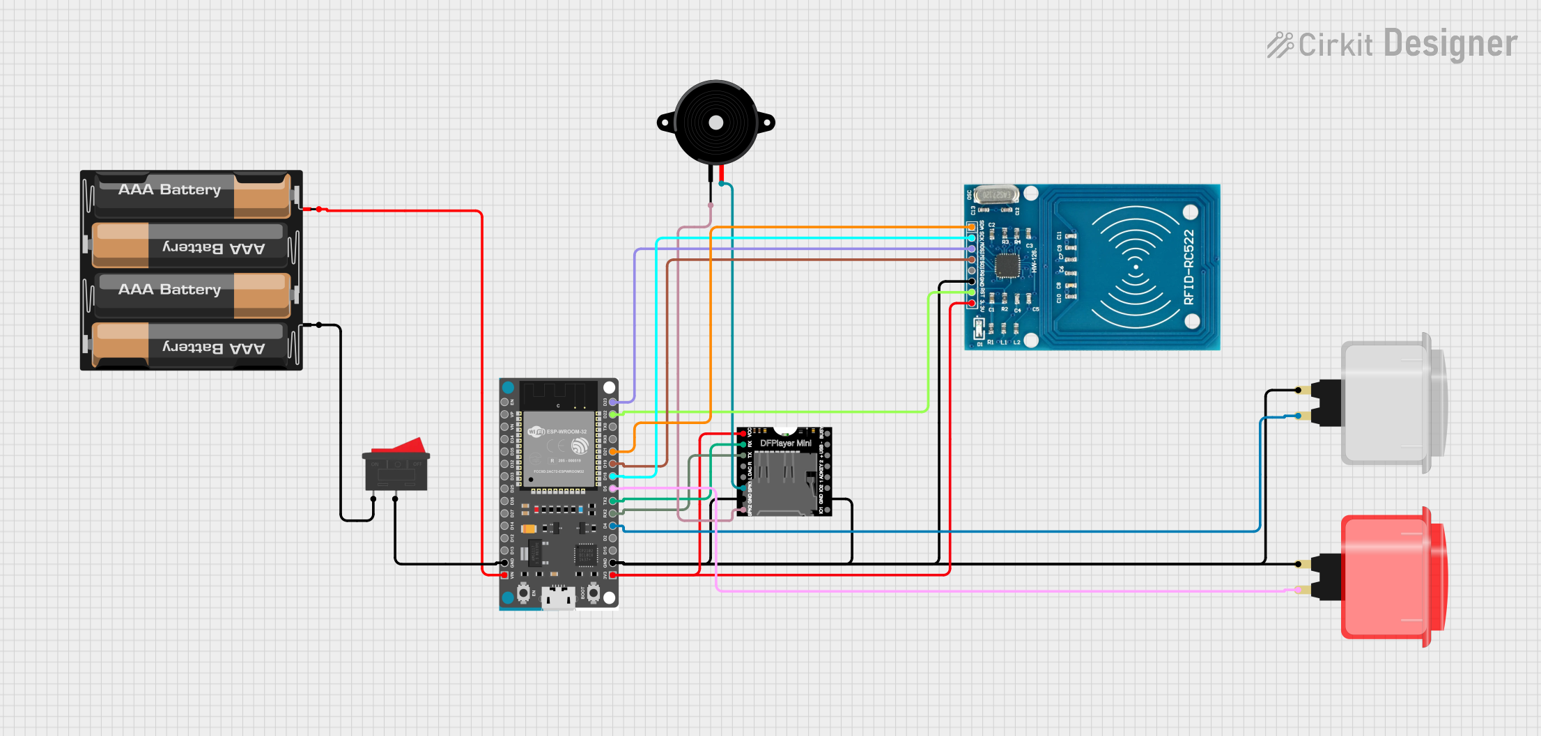
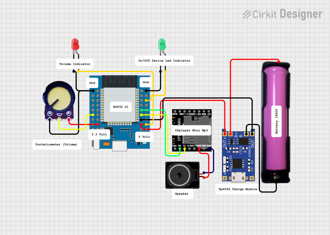
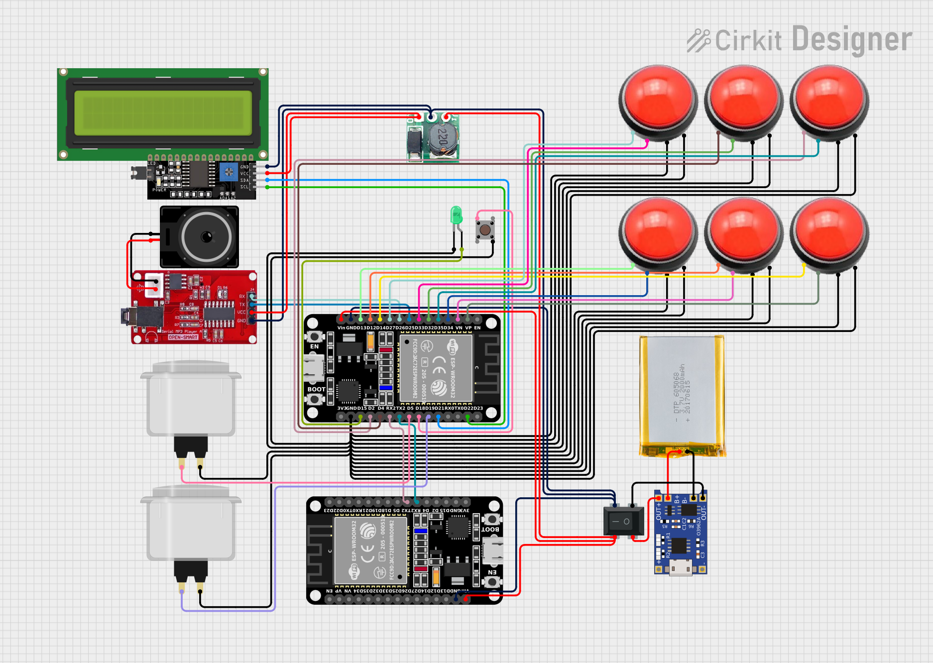
Explore Projects Built with SparkFun ESP32 Thing
Common Applications and Use Cases
- IoT devices and smart home automation
- Wireless data logging and monitoring
- Bluetooth-enabled applications
- Prototyping and development of connected devices
- Robotics and sensor networks
Technical Specifications
The SparkFun ESP32 Thing is packed with features to support a wide range of applications. Below are the key technical specifications:
| Specification | Details |
|---|---|
| Microcontroller | ESP32-D0WDQ6 (dual-core, 32-bit Xtensa LX6) |
| Clock Speed | Up to 240 MHz |
| Flash Memory | 4 MB |
| SRAM | 520 KB |
| Wi-Fi | 802.11 b/g/n |
| Bluetooth | Bluetooth v4.2 (Classic and BLE) |
| Operating Voltage | 3.3V |
| Input Voltage (USB) | 5V |
| GPIO Pins | 21 (including ADC, DAC, PWM, I2C, SPI, UART) |
| ADC Channels | 18 (12-bit resolution) |
| DAC Channels | 2 |
| Communication Interfaces | UART, SPI, I2C, I2S, CAN |
| Power Supply Options | USB or LiPo battery (via onboard JST connector) |
| Dimensions | 2.3" x 0.9" (58.4 mm x 22.9 mm) |
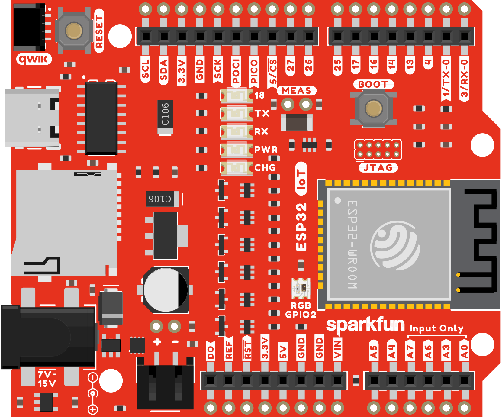
Pin Configuration and Descriptions
The SparkFun ESP32 Thing has a variety of pins for different functionalities. Below is a summary of the pin configuration:
| Pin | Function | Description |
|---|---|---|
| VIN | Power Input | Accepts 5V from USB or external power source. |
| 3.3V | Power Output | Provides regulated 3.3V output. |
| GND | Ground | Common ground for the circuit. |
| EN | Enable | Resets the board when pulled low. |
| IO0 | GPIO0 / Boot | Used for boot mode selection or general-purpose I/O. |
| IO2 | GPIO2 | General-purpose I/O pin. |
| IO4 | GPIO4 | General-purpose I/O pin. |
| IO12 | GPIO12 / ADC / Touch | Can be used as ADC or capacitive touch input. |
| IO13 | GPIO13 / ADC / Touch | Can be used as ADC or capacitive touch input. |
| IO14 | GPIO14 / ADC / Touch | Can be used as ADC or capacitive touch input. |
| IO15 | GPIO15 / ADC / Touch | Can be used as ADC or capacitive touch input. |
| IO16 | GPIO16 | General-purpose I/O pin. |
| IO17 | GPIO17 | General-purpose I/O pin. |
| TXD0 | UART0 TX | Transmit pin for UART0. |
| RXD0 | UART0 RX | Receive pin for UART0. |
| SDA | I2C Data | Data line for I2C communication. |
| SCL | I2C Clock | Clock line for I2C communication. |
| MOSI | SPI Master Out, Slave In | Data output for SPI communication. |
| MISO | SPI Master In, Slave Out | Data input for SPI communication. |
| SCK | SPI Clock | Clock line for SPI communication. |
Usage Instructions
How to Use the SparkFun ESP32 Thing in a Circuit
Powering the Board:
- Connect the board to your computer via a micro-USB cable for power and programming.
- Alternatively, use a 3.7V LiPo battery with the onboard JST connector for portable applications.
Programming the Board:
- Install the ESP32 board support package in the Arduino IDE or use the ESP-IDF (Espressif IoT Development Framework) for advanced development.
- Select "SparkFun ESP32 Thing" as the board in the Arduino IDE.
- Connect the board to your computer and upload your code.
Connecting Peripherals:
- Use the GPIO pins to connect sensors, actuators, or other devices.
- Ensure that the voltage levels of connected devices are compatible with the 3.3V logic of the ESP32.
Using Wi-Fi and Bluetooth:
- Use the built-in libraries (e.g.,
WiFi.handBluetoothSerial.hin Arduino) to enable wireless communication. - Configure the network credentials or Bluetooth pairing settings in your code.
- Use the built-in libraries (e.g.,
Important Considerations and Best Practices
- Voltage Levels: The GPIO pins operate at 3.3V. Avoid connecting 5V devices directly to the pins without a level shifter.
- Boot Mode: Ensure GPIO0 is pulled low during boot to enter programming mode.
- Power Supply: If using a LiPo battery, monitor the battery voltage to prevent over-discharge.
- Heat Management: The ESP32 chip may get warm during operation. Ensure proper ventilation if used in an enclosure.
Example Code for Arduino UNO Integration
Below is an example of how to use the SparkFun ESP32 Thing to connect to a Wi-Fi network and send data to a server:
#include <WiFi.h> // Include the Wi-Fi library

// Replace with your network credentials
const char* ssid = "Your_SSID";
const char* password = "Your_PASSWORD";

void setup() {
  Serial.begin(115200); // Initialize serial communication
  delay(1000);

  // Connect to Wi-Fi
  Serial.println("Connecting to Wi-Fi...");
  WiFi.begin(ssid, password);

  while (WiFi.status() != WL_CONNECTED) {
    delay(500);
    Serial.print(".");
  }

  Serial.println("\nWi-Fi connected!");
  Serial.print("IP Address: ");
  Serial.println(WiFi.localIP()); // Print the device's IP address
}

void loop() {
  // Add your main code here
}
Troubleshooting and FAQs
Common Issues and Solutions
The board is not detected by the computer:
- Ensure the USB cable is functional and supports data transfer.
- Install the necessary USB-to-serial drivers (e.g., CP2102 driver).
Upload fails with a timeout error:
- Check that the correct board and COM port are selected in the Arduino IDE.
- Hold down the "BOOT" button on the board while uploading the code.
Wi-Fi connection fails:
- Double-check the SSID and password in your code.
- Ensure the Wi-Fi network is within range and not using unsupported security protocols.
GPIO pins not working as expected:
- Verify that the pins are not being used for other functions (e.g., boot mode).
- Check for shorts or incorrect wiring in your circuit.
FAQs
Q: Can I power the board with a 5V power supply?
A: Yes, you can power the board via the VIN pin or USB port with a 5V supply. The onboard regulator will step it down to 3.3V.
Q: Does the board support OTA (Over-the-Air) updates?
A: Yes, the ESP32 supports OTA updates. You can use libraries like ArduinoOTA to implement this feature.
Q: Can I use the board with MicroPython?
A: Yes, the ESP32 is compatible with MicroPython. You can flash the MicroPython firmware to the board and use it for development.
Q: How do I reset the board?
A: Press the "EN" button on the board to reset it.