How to Use BZ-215 GPS: Examples, Pinouts, and Specs
Introduction
The BZ-215 GPS is a compact and highly efficient global positioning system (GPS) module designed to provide accurate location data for a wide range of applications. With its high sensitivity and low power consumption, the BZ-215 GPS is ideal for navigation, tracking, and geolocation projects. It supports multiple communication protocols, making it easy to integrate into various electronic systems, including microcontroller-based platforms like Arduino.
Explore Projects Built with BZ-215 GPS


Explore Projects Built with BZ-215 GPS
Common Applications
- Vehicle tracking and fleet management
- Personal navigation devices
- Drones and UAVs
- IoT devices requiring geolocation
- Outdoor sports and fitness trackers
Technical Specifications
The BZ-215 GPS module is designed to deliver reliable performance in a compact form factor. Below are its key technical details:
| Parameter | Specification |
|---|---|
| Operating Voltage | 3.3V to 5.0V |
| Current Consumption | 25mA (typical) |
| Positioning Accuracy | ±2.5 meters |
| Communication Protocols | UART, I2C, SPI |
| Baud Rate (Default) | 9600 bps |
| Sensitivity | -165 dBm |
| Update Rate | 1 Hz to 10 Hz |
| Operating Temperature | -40°C to +85°C |
| Dimensions | 25mm x 25mm x 5mm |
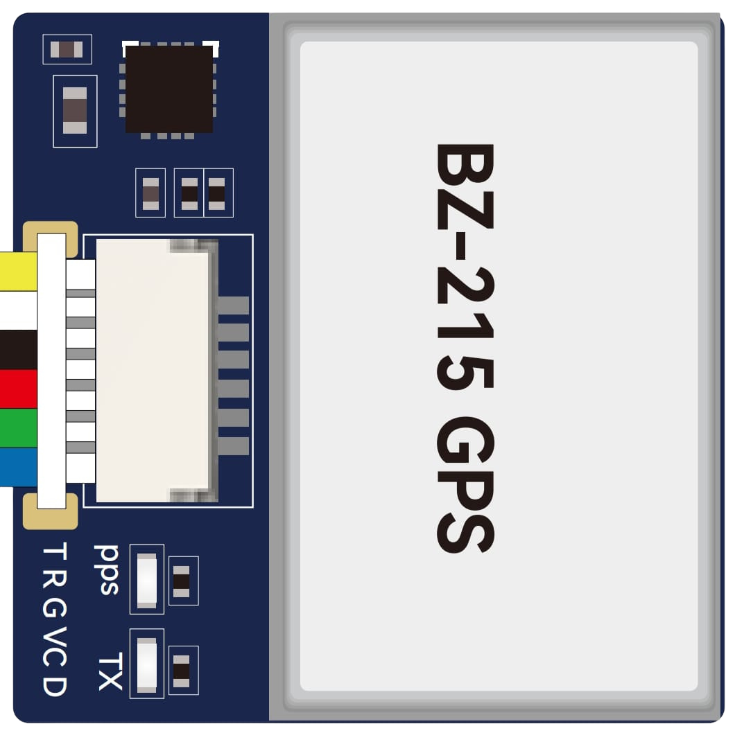
Pin Configuration
The BZ-215 GPS module has a simple pinout for easy integration. Below is the pin configuration:
| Pin | Name | Description |
|---|---|---|
| 1 | VCC | Power supply input (3.3V to 5.0V) |
| 2 | GND | Ground connection |
| 3 | TX | UART Transmit (data output) |
| 4 | RX | UART Receive (data input) |
| 5 | PPS | Pulse Per Second output for timing synchronization |
| 6 | SDA | I2C Data line |
| 7 | SCL | I2C Clock line |
| 8 | SPI_CS | SPI Chip Select |
| 9 | SPI_MOSI | SPI Master Out Slave In |
| 10 | SPI_MISO | SPI Master In Slave Out |
| 11 | SPI_CLK | SPI Clock |
Usage Instructions
How to Use the BZ-215 GPS in a Circuit
- Power the Module: Connect the VCC pin to a 3.3V or 5.0V power source and the GND pin to ground.
- Choose Communication Protocol: Select the desired communication protocol (UART, I2C, or SPI) based on your project requirements.
- For UART, connect the TX and RX pins to the corresponding UART pins on your microcontroller.
- For I2C, connect the SDA and SCL pins to the I2C bus.
- For SPI, connect SPI_CS, SPI_MOSI, SPI_MISO, and SPI_CLK to the SPI interface.
- Configure the Module: Use the default baud rate of 9600 bps for UART communication or configure the module as needed using AT commands.
- Read GPS Data: Parse the NMEA sentences (e.g., GPGGA, GPRMC) output by the module to extract location, time, and other data.
Important Considerations
- Ensure the module has a clear view of the sky for optimal satellite reception.
- Use decoupling capacitors near the VCC pin to reduce noise and ensure stable operation.
- Avoid placing the module near high-frequency noise sources, such as switching power supplies or motors.
- If using the PPS pin for timing, ensure your microcontroller can handle the pulse signal.
Example: Connecting to an Arduino UNO
Below is an example of how to connect the BZ-215 GPS module to an Arduino UNO using UART:
Wiring
| BZ-215 Pin | Arduino Pin |
|---|---|
| VCC | 5V |
| GND | GND |
| TX | Pin 10 (RX) |
| RX | Pin 11 (TX) |
Code Example
#include <SoftwareSerial.h>

// Define RX and TX pins for SoftwareSerial
SoftwareSerial gpsSerial(10, 11); // RX = Pin 10, TX = Pin 11

void setup() {
  Serial.begin(9600); // Start Serial Monitor at 9600 bps
  gpsSerial.begin(9600); // Start GPS module communication at 9600 bps

  Serial.println("BZ-215 GPS Module Initialized");
}

void loop() {
  // Check if data is available from the GPS module
  while (gpsSerial.available()) {
    char c = gpsSerial.read(); // Read one character from GPS
    Serial.print(c); // Print the character to the Serial Monitor

    // Note: GPS data is output as NMEA sentences. You can parse these
    // sentences to extract specific information like latitude, longitude,
    // and time.
  }
}
Troubleshooting and FAQs
Common Issues and Solutions
No GPS Data Output
- Cause: The module may not have a clear view of the sky.
- Solution: Move the module to an open area with minimal obstructions.
Incorrect or Inconsistent Location Data
- Cause: Poor satellite signal or interference.
- Solution: Ensure the module is away from sources of RF interference and has a stable power supply.
Module Not Responding
- Cause: Incorrect wiring or baud rate mismatch.
- Solution: Double-check the connections and ensure the baud rate matches the module's configuration.
PPS Signal Not Detected
- Cause: PPS pin not connected or microcontroller not configured to read the signal.
- Solution: Verify the PPS pin connection and ensure your microcontroller is set up to handle the pulse.
FAQs
Q: Can the BZ-215 GPS module work indoors?
A: While the module may work indoors near windows, its performance is significantly better outdoors with a clear view of the sky.
Q: How do I change the baud rate of the module?
A: You can use AT commands sent via UART to configure the baud rate. Refer to the module's AT command set for details.
Q: What is the purpose of the PPS pin?
A: The PPS (Pulse Per Second) pin provides a precise timing signal that can be used for synchronization in time-sensitive applications.
Q: Can I use the BZ-215 GPS with a 3.3V microcontroller?
A: Yes, the module supports both 3.3V and 5.0V logic levels, making it compatible with a wide range of microcontrollers.