How to Use ACS71: Examples, Pinouts, and Specs
Introduction
The ACS71 is a Hall effect-based current sensor manufactured by Allegro MicroSystems. It is designed to provide accurate and reliable current measurement in high-voltage applications. The sensor offers galvanic isolation, making it suitable for applications where electrical isolation is critical. The ACS71 can measure both AC and DC currents, with a linear output voltage proportional to the sensed current.
Explore Projects Built with ACS71

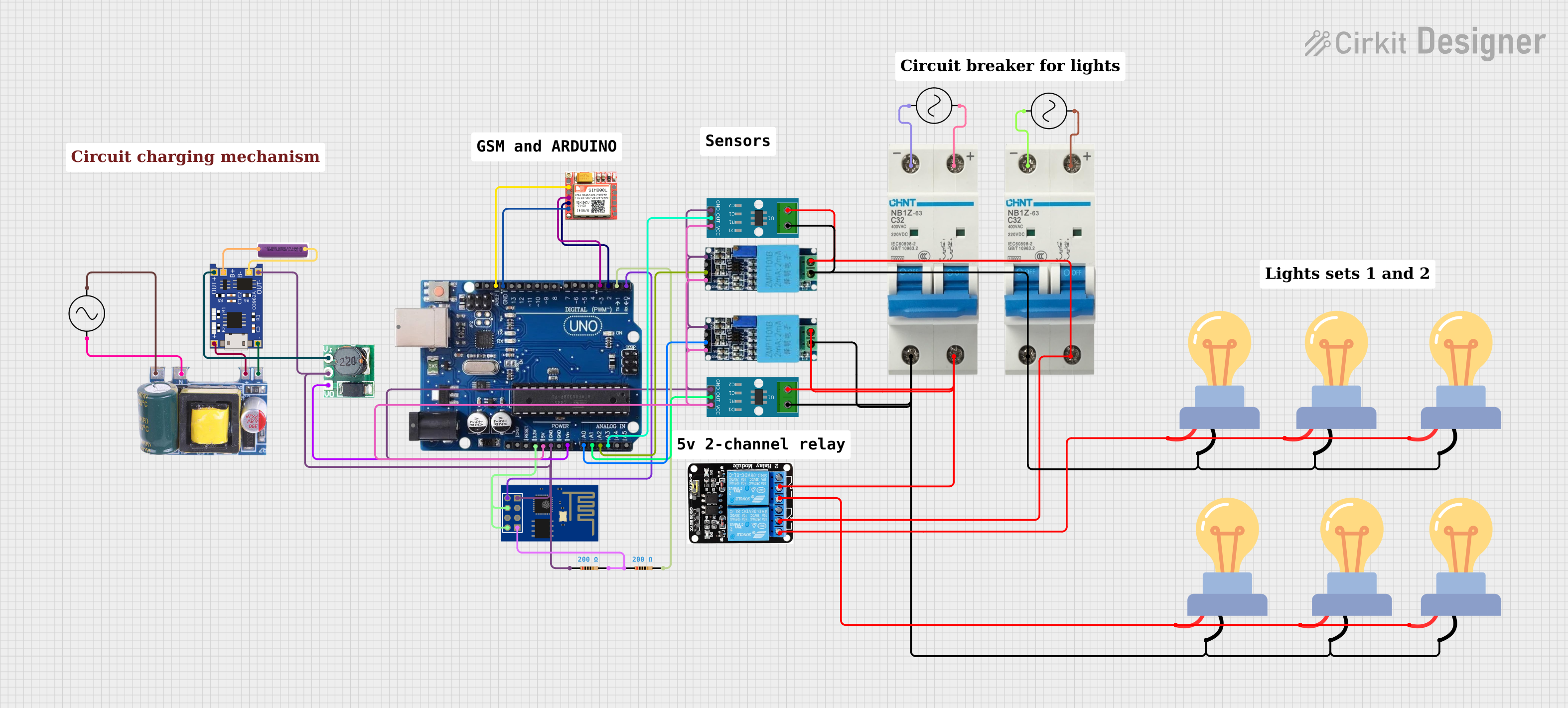
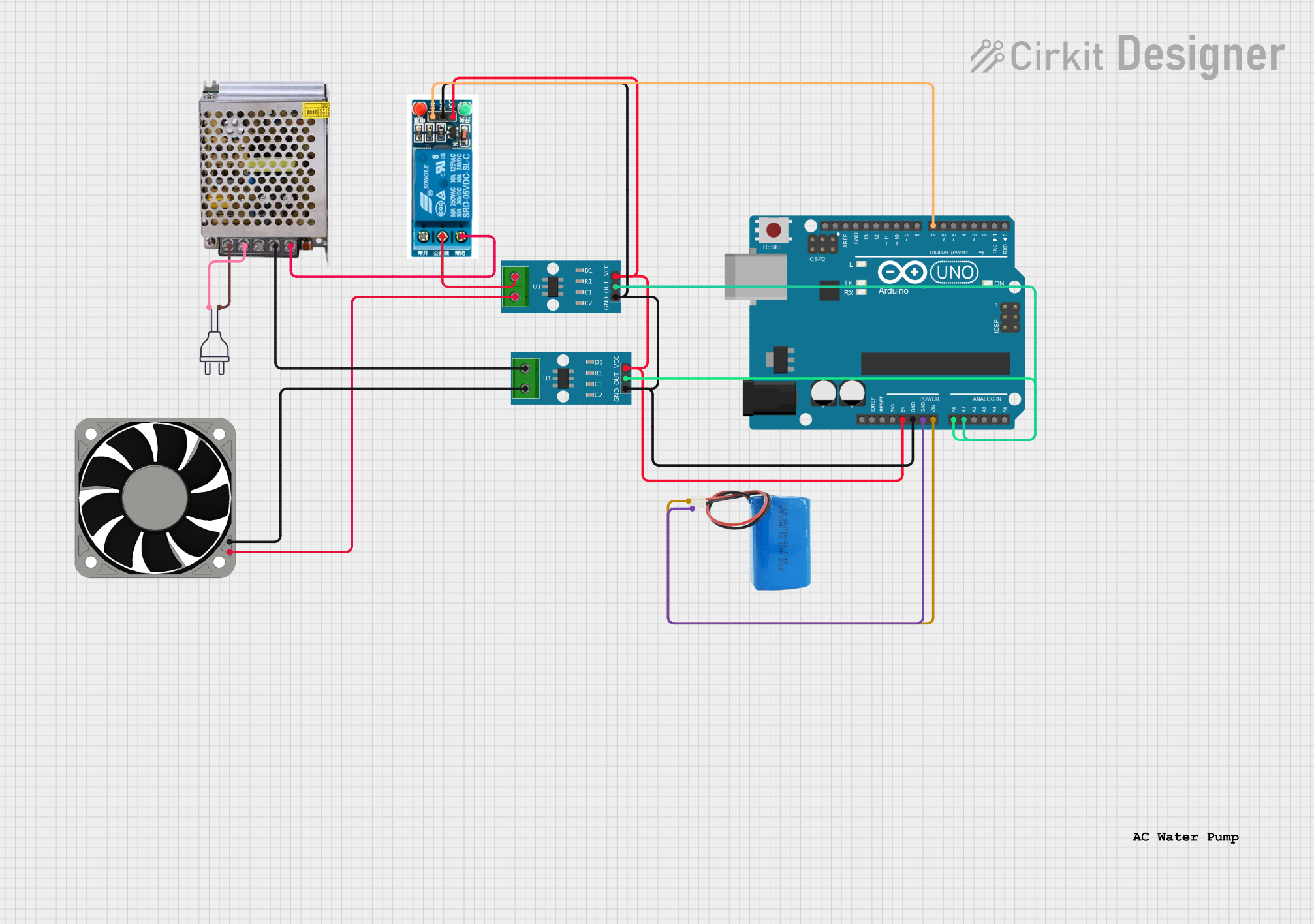

Explore Projects Built with ACS71
Common Applications
- Motor control and monitoring
- Power supply and inverter systems
- Overcurrent protection circuits
- Battery management systems
- Industrial automation and robotics
Technical Specifications
The ACS71 is available in multiple variants to support different current ranges. Below are the key technical specifications:
| Parameter | Value |
|---|---|
| Supply Voltage (Vcc) | 4.5 V to 5.5 V |
| Current Measurement Range | ±50 A, ±100 A, or ±200 A (varies by model) |
| Sensitivity | 20 mV/A to 40 mV/A (model-dependent) |
| Output Voltage Range | 0.5 V to 4.5 V |
| Isolation Voltage | 2.1 kV RMS |
| Response Time | 3 µs |
| Operating Temperature Range | -40°C to +125°C |
Pin Configuration and Descriptions
The ACS71 is typically available in an SOIC-8 package. The pinout and descriptions are as follows:
| Pin Number | Pin Name | Description |
|---|---|---|
| 1 | Vcc | Power supply input (4.5 V to 5.5 V). |
| 2 | GND | Ground connection. |
| 3 | VIOUT | Analog output voltage proportional to sensed current. |
| 4 | FILTER | Optional external capacitor for noise filtering. |
| 5-8 | IP+ / IP- | Current-carrying terminals for the primary current path. |
Usage Instructions
How to Use the ACS71 in a Circuit
- Power Supply: Connect the Vcc pin to a regulated 5 V power supply and the GND pin to the circuit ground.
- Current Path: Pass the current to be measured through the IP+ and IP- terminals. Ensure the current does not exceed the sensor's rated range.
- Output Signal: The VIOUT pin provides an analog voltage proportional to the sensed current. This output can be read using an ADC (Analog-to-Digital Converter) on a microcontroller.
- Filtering: For improved noise performance, connect a capacitor (typically 1 nF to 10 nF) between the FILTER pin and GND.
Important Considerations
- Isolation: The ACS71 provides galvanic isolation between the primary current path and the output signal, making it safe for high-voltage applications.
- Accuracy: To achieve optimal accuracy, ensure the sensor is mounted away from strong magnetic fields or sources of electrical noise.
- Thermal Management: The sensor may heat up during operation, especially at high currents. Ensure adequate ventilation or heat dissipation in your design.
Example: Connecting the ACS71 to an Arduino UNO
Below is an example of how to interface the ACS71 with an Arduino UNO to measure current:
Circuit Connections
- Connect the Vcc pin of the ACS71 to the Arduino's 5V pin.
- Connect the GND pin of the ACS71 to the Arduino's GND.
- Connect the VIOUT pin of the ACS71 to an analog input pin on the Arduino (e.g., A0).
- Pass the current to be measured through the IP+ and IP- terminals.
Arduino Code
// Define the analog input pin connected to the ACS71 output
const int currentSensorPin = A0;

// Define the sensitivity of the ACS71 (in mV/A). Adjust based on your model.
const float sensitivity = 20.0; // Example: 20 mV/A for ±50 A model

// Define the zero-current output voltage (in volts)
const float zeroCurrentVoltage = 2.5; // Typically 2.5 V for ACS71

void setup() {
  Serial.begin(9600); // Initialize serial communication
}

void loop() {
  // Read the analog value from the sensor
  int sensorValue = analogRead(currentSensorPin);

  // Convert the analog value to voltage (assuming 5V reference)
  float sensorVoltage = sensorValue * (5.0 / 1023.0);

  // Calculate the current (in amps)
  float current = (sensorVoltage - zeroCurrentVoltage) / (sensitivity / 1000.0);

  // Print the current to the Serial Monitor
  Serial.print("Current: ");
  Serial.print(current);
  Serial.println(" A");

  delay(500); // Wait for 500 ms before the next reading
}
Troubleshooting and FAQs
Common Issues
No Output Signal:
- Ensure the Vcc and GND pins are properly connected to a 5 V power supply.
- Verify that the current path is correctly connected to the IP+ and IP- terminals.
Inaccurate Readings:
- Check for strong magnetic fields or electrical noise near the sensor.
- Verify the sensitivity value used in calculations matches the sensor's model.
Output Voltage Saturation:
- Ensure the current being measured does not exceed the sensor's rated range.
FAQs
Q: Can the ACS71 measure both AC and DC currents?
A: Yes, the ACS71 can measure both AC and DC currents with a linear output proportional to the sensed current.
Q: What happens if the current exceeds the sensor's range?
A: The output voltage will saturate at the maximum or minimum value (0.5 V or 4.5 V), and the measurement will no longer be accurate.
Q: Is an external capacitor required for the FILTER pin?
A: While not mandatory, adding a capacitor (1 nF to 10 nF) can help reduce noise and improve signal stability.
Q: Can the ACS71 be used in high-voltage applications?
A: Yes, the ACS71 provides galvanic isolation and is rated for an isolation voltage of 2.1 kV RMS, making it suitable for high-voltage environments.