Cirkit Designer Logo
Cirkit Designer
Your all-in-one circuit design IDE
Home / 
Component Documentation

How to Use Power_unit: Examples, Pinouts, and Specs

Image of Power_unit
Cirkit Designer LogoDesign with Power_unit in Cirkit Designer

Introduction

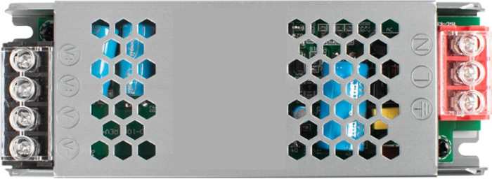
A Power Unit is a device that supplies electrical energy to a circuit, converting various forms of energy (like AC or DC) into usable power for electronic components. It is a critical component in any electronic system, ensuring that all connected devices receive the appropriate voltage and current for proper operation. Power Units are commonly used in applications such as powering microcontrollers, sensors, motors, and other electronic devices.

Explore Projects Built with Power_unit

Use Cirkit Designer to design, explore, and prototype these projects online. Some projects support real-time simulation. Click "Open Project" to start designing instantly!
Battery-Powered UPS with Step-Down Buck Converter and BMS
Image of Mini ups: A project utilizing Power_unit in a practical application
This circuit is a power management system that steps down a 240V AC input to a lower DC voltage using a buck converter, which then powers a 40W UPS. The UPS is controlled by a rocker switch and is backed up by a battery management system (BMS) connected to three 3.7V batteries in series, ensuring continuous power supply.
Cirkit Designer LogoOpen Project in Cirkit Designer
USB-Powered DC Gear Motor with LED Indicator
Image of Hand Crank mobile charger : A project utilizing Power_unit in a practical application
This circuit appears to be a power supply unit with a bridge rectifier connected to a DC gear motor, indicating it is designed to convert AC to DC power for the motor. An electrolytic capacitor is used for smoothing the DC output, and a 7805 voltage regulator is included to provide a stable 5V output. Additionally, there is an LED with a series resistor, likely serving as a power indicator light.
Cirkit Designer LogoOpen Project in Cirkit Designer
12V UPS System with Dual 18650 Li-ion Battery Backup and Voltage Regulation
Image of Power supply: A project utilizing Power_unit in a practical application
This circuit is designed to provide an uninterruptible power supply (UPS) system with a 12V DC output. It includes a 12V 5A power supply connected to an AC source through a toggle switch, which charges a pair of 18650 Li-ion batteries via a voltage regulator (XL4016). The UPS module ensures a continuous power supply to the load by switching between the power supply and the battery bank.
Cirkit Designer LogoOpen Project in Cirkit Designer
Battery-Powered USB Charger with LED Indicator and DC Motor
Image of Copy of Hand Crank mobile charger : A project utilizing Power_unit in a practical application
This circuit converts AC power to DC using a bridge rectifier and regulates the voltage to 5V with a 7805 voltage regulator. It powers a USB port and indicates power status with an LED, while also providing a charging interface through a multi-charging cable.
Cirkit Designer LogoOpen Project in Cirkit Designer

Explore Projects Built with Power_unit

Use Cirkit Designer to design, explore, and prototype these projects online. Some projects support real-time simulation. Click "Open Project" to start designing instantly!
Image of Mini ups: A project utilizing Power_unit in a practical application
Battery-Powered UPS with Step-Down Buck Converter and BMS
This circuit is a power management system that steps down a 240V AC input to a lower DC voltage using a buck converter, which then powers a 40W UPS. The UPS is controlled by a rocker switch and is backed up by a battery management system (BMS) connected to three 3.7V batteries in series, ensuring continuous power supply.
Cirkit Designer LogoOpen Project in Cirkit Designer
Image of Hand Crank mobile charger : A project utilizing Power_unit in a practical application
USB-Powered DC Gear Motor with LED Indicator
This circuit appears to be a power supply unit with a bridge rectifier connected to a DC gear motor, indicating it is designed to convert AC to DC power for the motor. An electrolytic capacitor is used for smoothing the DC output, and a 7805 voltage regulator is included to provide a stable 5V output. Additionally, there is an LED with a series resistor, likely serving as a power indicator light.
Cirkit Designer LogoOpen Project in Cirkit Designer
Image of Power supply: A project utilizing Power_unit in a practical application
12V UPS System with Dual 18650 Li-ion Battery Backup and Voltage Regulation
This circuit is designed to provide an uninterruptible power supply (UPS) system with a 12V DC output. It includes a 12V 5A power supply connected to an AC source through a toggle switch, which charges a pair of 18650 Li-ion batteries via a voltage regulator (XL4016). The UPS module ensures a continuous power supply to the load by switching between the power supply and the battery bank.
Cirkit Designer LogoOpen Project in Cirkit Designer
Image of Copy of Hand Crank mobile charger : A project utilizing Power_unit in a practical application
Battery-Powered USB Charger with LED Indicator and DC Motor
This circuit converts AC power to DC using a bridge rectifier and regulates the voltage to 5V with a 7805 voltage regulator. It powers a USB port and indicates power status with an LED, while also providing a charging interface through a multi-charging cable.
Cirkit Designer LogoOpen Project in Cirkit Designer

Common Applications and Use Cases

  • Powering microcontroller boards (e.g., Arduino, Raspberry Pi)
  • Supplying energy to sensors and actuators in IoT systems
  • Providing stable voltage for industrial control systems
  • Charging batteries in portable devices
  • Powering LED lighting systems

Technical Specifications

Below are the key technical details of a typical Power Unit:

Parameter Specification
Input Voltage Range 100-240V AC (for AC-DC units)
Output Voltage Range 3.3V, 5V, 12V, or adjustable
Output Current 0.5A to 10A (depending on model)
Power Rating 5W to 120W
Efficiency Up to 90%
Ripple and Noise <50mV (typical)
Protection Features Overvoltage, Overcurrent, Short Circuit
Operating Temperature -20°C to 70°C
Dimensions Varies by model

Pin Configuration and Descriptions

The pin configuration for a standard DC Power Unit is as follows:

Pin Label Description
1 VIN Input voltage (e.g., 100-240V AC or DC input)
2 GND Ground connection for input
3 VOUT Regulated output voltage (e.g., 5V, 12V)
4 GND Ground connection for output

Usage Instructions

How to Use the Power Unit in a Circuit

  1. Connect the Input Voltage: Ensure the input voltage matches the Power Unit's specifications. For AC-DC units, connect the AC mains to the VIN and GND input terminals.
  2. Connect the Output Voltage: Attach the VOUT and GND terminals to the load (e.g., microcontroller, sensor, or motor).
  3. Verify Polarity: Double-check the polarity of the connections to avoid damage to the Power Unit or connected devices.
  4. Power On: Switch on the Power Unit and measure the output voltage with a multimeter to confirm proper operation before connecting sensitive components.

Important Considerations and Best Practices

  • Heat Dissipation: Ensure adequate ventilation or heat sinking to prevent overheating during operation.
  • Load Compatibility: Verify that the load's voltage and current requirements are within the Power Unit's output specifications.
  • Protection Features: Use a fuse or circuit breaker on the input side to protect against surges or short circuits.
  • Noise Filtering: For sensitive applications, consider adding capacitors or filters to reduce ripple and noise.

Example: Using a Power Unit with an Arduino UNO

Below is an example of how to connect a 5V Power Unit to an Arduino UNO:

  1. Connect the Power Unit's VOUT (5V) to the Arduino's 5V pin.
  2. Connect the Power Unit's GND to the Arduino's GND pin.
  3. Ensure the Power Unit is powered on and providing a stable 5V output.

Sample Arduino Code

// Example code to blink an LED using an Arduino UNO powered by a Power Unit

const int ledPin = 13; // Pin connected to the onboard LED

void setup() {
  pinMode(ledPin, OUTPUT); // Set the LED pin as an output
}

void loop() {
  digitalWrite(ledPin, HIGH); // Turn the LED on
  delay(1000);               // Wait for 1 second
  digitalWrite(ledPin, LOW);  // Turn the LED off
  delay(1000);               // Wait for 1 second
}

Troubleshooting and FAQs

Common Issues and Solutions

  1. No Output Voltage

    • Cause: Input voltage is not connected or is outside the specified range.
    • Solution: Verify the input voltage and connections. Ensure the Power Unit is switched on.
  2. Overheating

    • Cause: Excessive load or poor ventilation.
    • Solution: Reduce the load or improve airflow around the Power Unit.
  3. Output Voltage Fluctuations

    • Cause: Load exceeds the Power Unit's capacity or input voltage is unstable.
    • Solution: Use a load within the Power Unit's specifications and ensure a stable input voltage.
  4. Short Circuit Protection Triggered

    • Cause: Output terminals are shorted.
    • Solution: Disconnect the load, check for shorts, and reconnect properly.

FAQs

  • Q: Can I use a Power Unit to charge a battery?

    • A: Yes, but ensure the Power Unit's output voltage and current are suitable for the battery type.
  • Q: How do I know if my Power Unit is overloaded?

    • A: Check for symptoms like overheating, voltage drops, or the Power Unit shutting down.
  • Q: Can I use one Power Unit for multiple devices?

    • A: Yes, as long as the total current draw of all devices does not exceed the Power Unit's maximum output current.

This concludes the documentation for the Power Unit. Always follow safety guidelines when working with electrical components.