How to Use Common Bus 4 +: Examples, Pinouts, and Specs

Introduction
The Common Bus 4 + is a digital circuit component designed to enable multiple signals to share a single communication pathway. This component simplifies data transfer between various parts of a system by reducing the number of physical connections required. It is particularly useful in systems where efficient communication and space-saving designs are critical.
Explore Projects Built with Common Bus 4 +
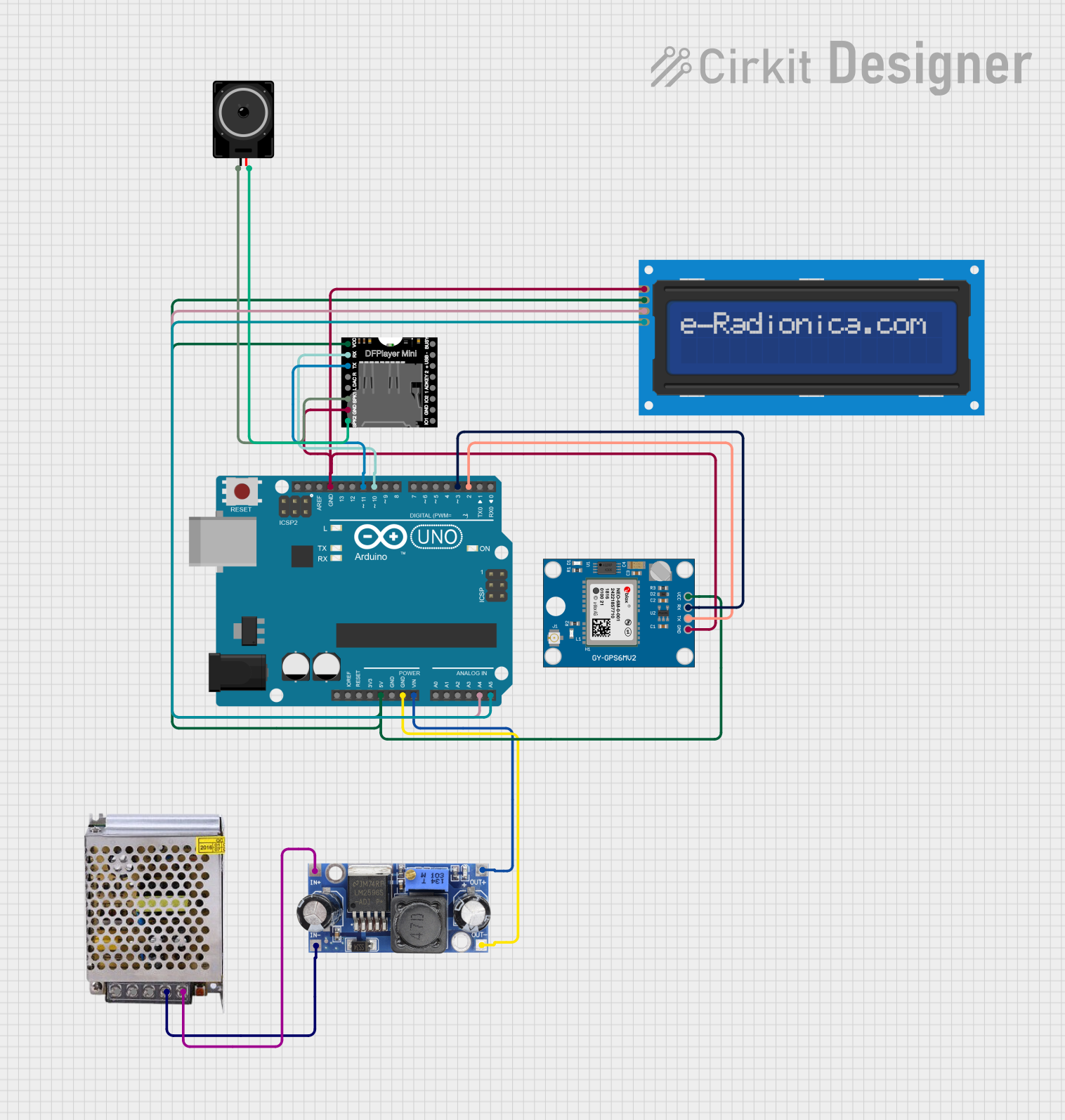
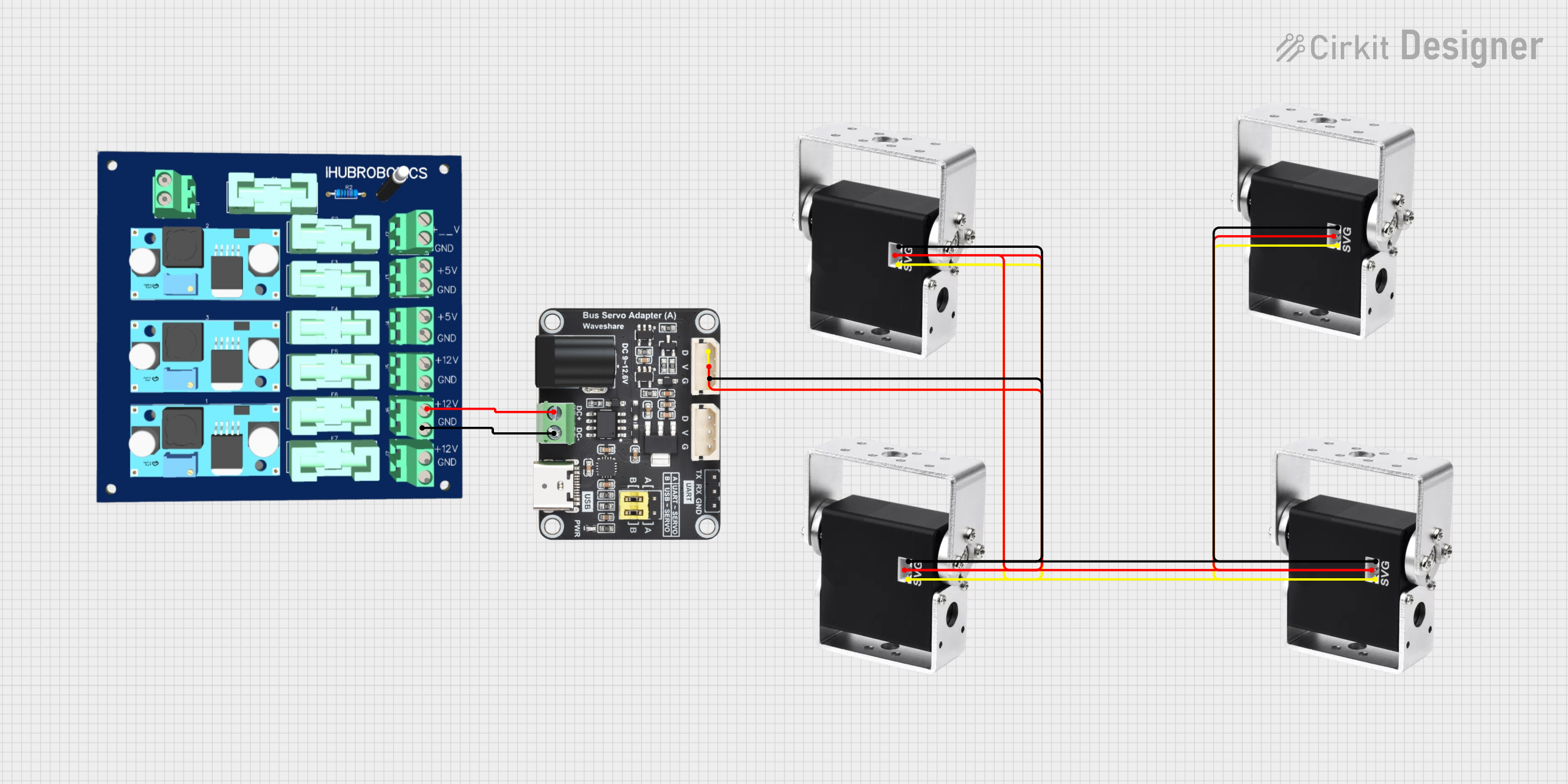


Explore Projects Built with Common Bus 4 +
Common Applications and Use Cases
- Microcontroller-based systems for signal routing
- Data transfer in embedded systems
- Communication between multiple sensors and actuators
- Simplifying wiring in complex circuits
- Use in educational projects to demonstrate bus communication principles
Technical Specifications
Key Technical Details
- Operating Voltage: 3.3V to 5V
- Maximum Current per Channel: 20mA
- Number of Channels: 4
- Signal Type: Digital
- Propagation Delay: < 10ns
- Operating Temperature Range: -40°C to 85°C
- Dimensions: 20mm x 10mm x 5mm
Pin Configuration and Descriptions
The Common Bus 4 + has a total of 8 pins, as described in the table below:
| Pin Number | Pin Name | Description |
|---|---|---|
| 1 | VCC | Power supply input (3.3V to 5V) |
| 2 | GND | Ground connection |
| 3 | IN1 | Input signal for Channel 1 |
| 4 | IN2 | Input signal for Channel 2 |
| 5 | IN3 | Input signal for Channel 3 |
| 6 | IN4 | Input signal for Channel 4 |
| 7 | OUT | Shared output for all input channels |
| 8 | ENABLE | Enable pin to activate the bus (HIGH to enable, LOW to disable) |
Usage Instructions
How to Use the Component in a Circuit
- Power the Component: Connect the
VCCpin to a 3.3V or 5V power source and theGNDpin to the ground of your circuit. - Connect Input Signals: Attach the digital signals you want to share on the bus to the
IN1,IN2,IN3, andIN4pins. - Enable the Bus: Set the
ENABLEpin to HIGH to activate the bus. When enabled, the signals from the input channels will be routed to the sharedOUTpin. - Read the Output: Connect the
OUTpin to the desired destination in your circuit to receive the shared signal.
Important Considerations and Best Practices
- Ensure that the input signals are within the operating voltage range of the component.
- Avoid exceeding the maximum current rating of 20mA per channel to prevent damage.
- Use pull-up or pull-down resistors on the
ENABLEpin if it is not actively controlled by a microcontroller. - Minimize the length of wires connected to the
OUTpin to reduce signal degradation. - If using with an Arduino UNO, ensure the
ENABLEpin is connected to a digital output pin for control.
Example Arduino Code
Below is an example of how to use the Common Bus 4 + with an Arduino UNO to enable the bus and read signals:
// Define pin connections
const int enablePin = 7;  // Pin connected to ENABLE
const int outPin = A0;    // Pin connected to OUT
const int inPins[] = {2, 3, 4, 5}; // Pins connected to IN1, IN2, IN3, IN4

void setup() {
  // Initialize serial communication for debugging
  Serial.begin(9600);

  // Set pin modes
  pinMode(enablePin, OUTPUT);
  pinMode(outPin, INPUT);
  for (int i = 0; i < 4; i++) {
    pinMode(inPins[i], OUTPUT);
  }

  // Enable the bus
  digitalWrite(enablePin, HIGH);
}

void loop() {
  // Send test signals to the input pins
  for (int i = 0; i < 4; i++) {
    digitalWrite(inPins[i], HIGH); // Set input HIGH
    delay(500); // Wait for 500ms
    digitalWrite(inPins[i], LOW);  // Set input LOW
  }

  // Read the shared output signal
  int outputValue = digitalRead(outPin);
  Serial.print("Output Signal: ");
  Serial.println(outputValue);

  delay(1000); // Wait for 1 second before repeating
}
Troubleshooting and FAQs
Common Issues and Solutions
No Output Signal on the OUT Pin:
- Ensure the
ENABLEpin is set to HIGH. - Verify that the input signals are within the operating voltage range.
- Check for loose or incorrect connections.
- Ensure the
Signal Degradation or Noise:
- Use shorter wires for the
OUTpin to minimize interference. - Add decoupling capacitors near the power pins to stabilize the voltage supply.
- Use shorter wires for the
Component Overheating:
- Ensure the current through each channel does not exceed 20mA.
- Verify that the operating temperature is within the specified range.
FAQs
Q: Can the Common Bus 4 + handle analog signals?
A: No, the component is designed for digital signals only. For analog signals, consider using a multiplexer.
Q: What happens if multiple input channels are active simultaneously?
A: The output signal will depend on the logic levels of the active inputs. Avoid driving multiple inputs HIGH simultaneously to prevent undefined behavior.
Q: Can I use the Common Bus 4 + with a 3.3V microcontroller?
A: Yes, the component supports an operating voltage range of 3.3V to 5V, making it compatible with 3.3V systems.