Cirkit Designer Logo
Cirkit Designer
Your all-in-one circuit design IDE
Home / 
Component Documentation

How to Use Duinotech Arduino Compatible 24V 5A MOS Driver Module: Examples, Pinouts, and Specs

Image of Duinotech Arduino Compatible 24V 5A MOS Driver Module
Cirkit Designer LogoDesign with Duinotech Arduino Compatible 24V 5A MOS Driver Module in Cirkit Designer

Introduction

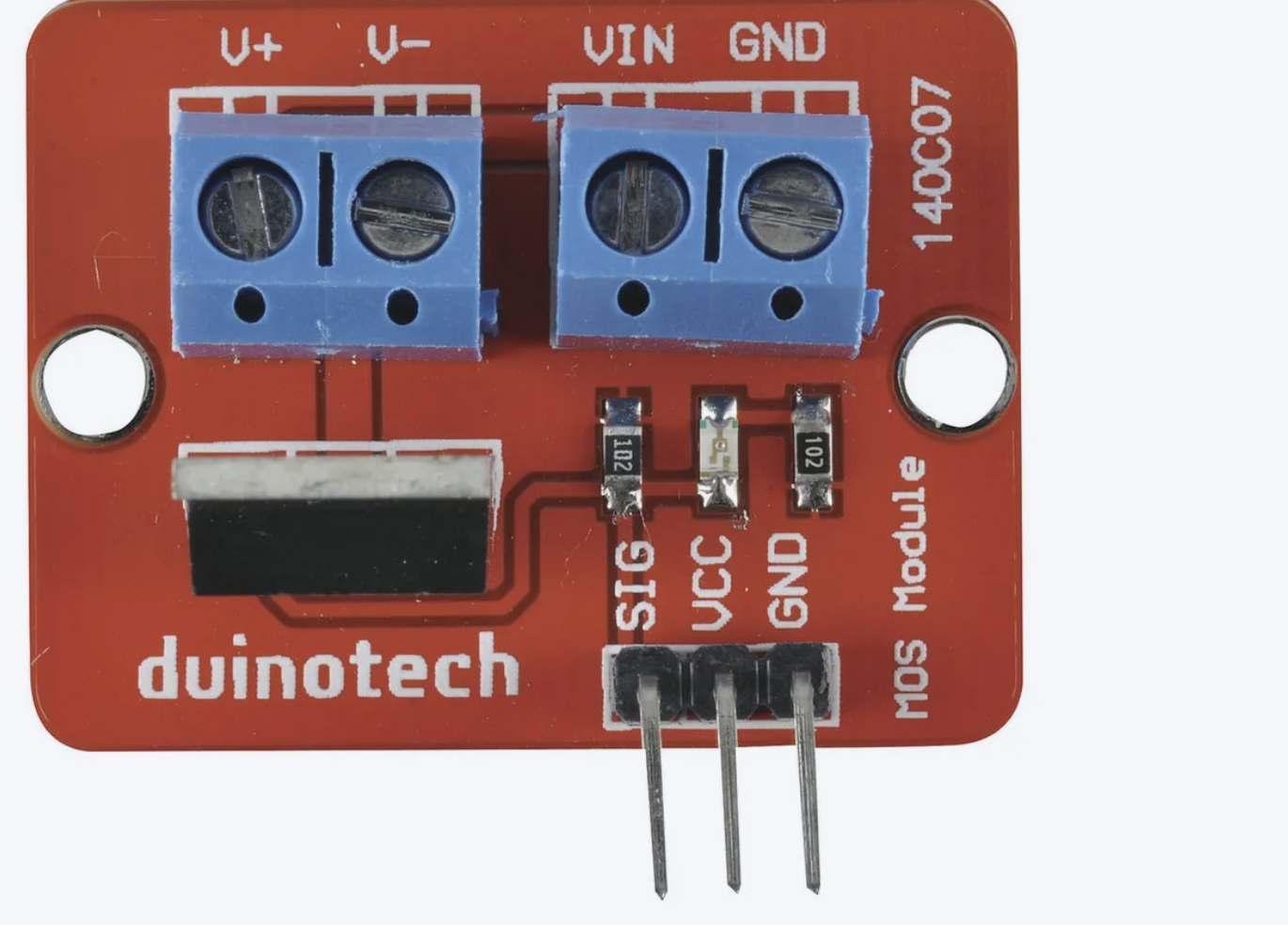
The Duinotech Arduino Compatible 24V 5A MOS Driver Module (Part ID: XC4488) is a high-performance MOSFET driver designed to control high-power loads with ease. It is capable of handling up to 24V and 5A, making it suitable for a wide range of applications, including robotics, automation, motor control, and LED lighting systems. This module is fully compatible with Arduino and other microcontroller platforms, enabling seamless integration into your projects.

Explore Projects Built with Duinotech Arduino Compatible 24V 5A MOS Driver Module

Use Cirkit Designer to design, explore, and prototype these projects online. Some projects support real-time simulation. Click "Open Project" to start designing instantly!
Arduino UNO Wi-Fi Controlled DC Motor Driver with Battery Management System
Image of RC Ball: A project utilizing Duinotech Arduino Compatible 24V 5A MOS Driver Module in a practical application
This circuit is a motor control system powered by a 3s 20A BMS and 18650 Li-ion batteries, which drives two DC Mini Metal Gear Motors using an L298N motor driver. The Arduino UNO R4 WiFi microcontroller is used to control the motor driver, and a buck converter provides regulated power to a Type-C port.
Cirkit Designer LogoOpen Project in Cirkit Designer
Arduino UNO Controlled Linear Actuator and Stepper Motor System with Multiple Pushbuttons
Image of CircuitV2_2761_GBB: A project utilizing Duinotech Arduino Compatible 24V 5A MOS Driver Module in a practical application
This circuit features an Arduino-based control system with multiple pushbuttons and resistors for input, a relay module for switching, and a linear actuator and stepper motor for mechanical movement. The EasyDriver module interfaces the stepper motor with the Arduino, while the relay controls the linear actuator. Power is supplied via a 12V power supply and a DC barrel jack.
Cirkit Designer LogoOpen Project in Cirkit Designer
Arduino-Controlled Solar-Powered Dual DC Motor Driver with Bluetooth Connectivity
Image of schematic diagram : A project utilizing Duinotech Arduino Compatible 24V 5A MOS Driver Module in a practical application
This circuit features an Arduino UNO microcontroller interfaced with an HC-05 Bluetooth module for wireless communication. It includes a solar panel charging system with a TP4056 charger module and NPF570 battery, regulated by a 24/12V buck converter. The L298N motor driver controls multiple DC motors, with power switching managed by a rocker switch.
Cirkit Designer LogoOpen Project in Cirkit Designer
Arduino Mega 2560 Multi-Motor Control System with NRF24L01 Wireless Module
Image of 24EWB10801: A project utilizing Duinotech Arduino Compatible 24V 5A MOS Driver Module in a practical application
This circuit is designed to control various types of motors using an Arduino Mega 2560 as the central microcontroller. It includes an NRF24L01 module for wireless communication, an L298N driver for controlling DC motors, a TB6612FNG driver for controlling DC Mini Metal Gear Motors, and an A4988 driver for controlling a bipolar stepper motor. Power is supplied by a 12V battery connected to the motor drivers and a 3.7V LiPo battery for the NRF24L01 module.
Cirkit Designer LogoOpen Project in Cirkit Designer

Explore Projects Built with Duinotech Arduino Compatible 24V 5A MOS Driver Module

Use Cirkit Designer to design, explore, and prototype these projects online. Some projects support real-time simulation. Click "Open Project" to start designing instantly!
Image of RC Ball: A project utilizing Duinotech Arduino Compatible 24V 5A MOS Driver Module in a practical application
Arduino UNO Wi-Fi Controlled DC Motor Driver with Battery Management System
This circuit is a motor control system powered by a 3s 20A BMS and 18650 Li-ion batteries, which drives two DC Mini Metal Gear Motors using an L298N motor driver. The Arduino UNO R4 WiFi microcontroller is used to control the motor driver, and a buck converter provides regulated power to a Type-C port.
Cirkit Designer LogoOpen Project in Cirkit Designer
Image of CircuitV2_2761_GBB: A project utilizing Duinotech Arduino Compatible 24V 5A MOS Driver Module in a practical application
Arduino UNO Controlled Linear Actuator and Stepper Motor System with Multiple Pushbuttons
This circuit features an Arduino-based control system with multiple pushbuttons and resistors for input, a relay module for switching, and a linear actuator and stepper motor for mechanical movement. The EasyDriver module interfaces the stepper motor with the Arduino, while the relay controls the linear actuator. Power is supplied via a 12V power supply and a DC barrel jack.
Cirkit Designer LogoOpen Project in Cirkit Designer
Image of schematic diagram : A project utilizing Duinotech Arduino Compatible 24V 5A MOS Driver Module in a practical application
Arduino-Controlled Solar-Powered Dual DC Motor Driver with Bluetooth Connectivity
This circuit features an Arduino UNO microcontroller interfaced with an HC-05 Bluetooth module for wireless communication. It includes a solar panel charging system with a TP4056 charger module and NPF570 battery, regulated by a 24/12V buck converter. The L298N motor driver controls multiple DC motors, with power switching managed by a rocker switch.
Cirkit Designer LogoOpen Project in Cirkit Designer
Image of 24EWB10801: A project utilizing Duinotech Arduino Compatible 24V 5A MOS Driver Module in a practical application
Arduino Mega 2560 Multi-Motor Control System with NRF24L01 Wireless Module
This circuit is designed to control various types of motors using an Arduino Mega 2560 as the central microcontroller. It includes an NRF24L01 module for wireless communication, an L298N driver for controlling DC motors, a TB6612FNG driver for controlling DC Mini Metal Gear Motors, and an A4988 driver for controlling a bipolar stepper motor. Power is supplied by a 12V battery connected to the motor drivers and a 3.7V LiPo battery for the NRF24L01 module.
Cirkit Designer LogoOpen Project in Cirkit Designer

Common Applications and Use Cases

  • Driving DC motors in robotics and automation systems
  • Controlling high-power LED strips or lighting systems
  • Switching solenoids, relays, or other inductive loads
  • General-purpose high-current switching in DIY electronics projects

Technical Specifications

The following table outlines the key technical specifications of the XC4488 MOS Driver Module:

Parameter Value
Operating Voltage 5V (logic level)
Load Voltage Range 5V to 24V
Maximum Load Current 5A
Control Signal Voltage 3.3V or 5V (logic compatible)
MOSFET Type N-Channel
Dimensions 33mm x 24mm x 10mm

Pin Configuration and Descriptions

The module features a simple 3-pin interface for control and a 2-pin terminal block for the load connection. The pinout is as follows:

Control Pins

Pin Name Description
1 GND Ground connection for the module and control signal.
2 IN Control input pin. Accepts 3.3V or 5V logic signals to switch the MOSFET.
3 VCC Power supply for the module's logic circuit (typically 5V).

Load Connection

Terminal Name Description
1 V+ Positive terminal of the load power supply (5V to 24V).
2 V- Negative terminal of the load, connected to the drain of the MOSFET.

Usage Instructions

How to Use the Component in a Circuit

  1. Power the Module: Connect the VCC pin to a 5V power source and the GND pin to the ground of your microcontroller.
  2. Connect the Load: Attach the positive terminal of your load's power supply to the V+ terminal and the negative terminal of your load to the V- terminal.
  3. Control the Module: Use a digital output pin from your Arduino (or other microcontroller) to send a HIGH or LOW signal to the IN pin. A HIGH signal will turn the MOSFET on, allowing current to flow through the load, while a LOW signal will turn it off.

Important Considerations and Best Practices

  • Ensure that the load does not exceed the module's maximum current rating of 5A.
  • Use a heat sink or active cooling if operating near the maximum current for extended periods.
  • For inductive loads (e.g., motors, solenoids), use a flyback diode across the load to protect the MOSFET from voltage spikes.
  • Verify that the control signal voltage matches the logic level of the module (3.3V or 5V).

Example Arduino Code

Below is an example of how to use the XC4488 MOS Driver Module with an Arduino UNO to control an LED strip:

// Define the control pin connected to the IN pin of the MOS Driver Module
const int controlPin = 9;

void setup() {
  // Set the control pin as an output
  pinMode(controlPin, OUTPUT);
}

void loop() {
  // Turn the load (e.g., LED strip) ON
  digitalWrite(controlPin, HIGH);
  delay(1000); // Keep it ON for 1 second

  // Turn the load OFF
  digitalWrite(controlPin, LOW);
  delay(1000); // Keep it OFF for 1 second
}

Note: Replace the LED strip with your desired load, ensuring it operates within the module's voltage and current limits.

Troubleshooting and FAQs

Common Issues and Solutions

  1. The load does not turn on:

    • Verify that the control signal voltage is correct (3.3V or 5V).
    • Check the connections to ensure the load is properly wired to the V+ and V- terminals.
    • Ensure the load's power supply is functioning and within the specified voltage range (5V to 24V).
  2. The MOSFET overheats:

    • Ensure the load current does not exceed 5A.
    • Add a heat sink or active cooling if operating near the maximum current for extended periods.
    • For inductive loads, ensure a flyback diode is installed to prevent voltage spikes.
  3. The module does not respond to control signals:

    • Confirm that the GND pin of the module is connected to the ground of the microcontroller.
    • Check the control signal wiring and ensure the Arduino pin is configured as an output.

FAQs

Q: Can I use this module with a 3.3V microcontroller like the ESP32?
A: Yes, the module is compatible with both 3.3V and 5V logic levels.

Q: Is it safe to use this module with inductive loads like motors?
A: Yes, but you must use a flyback diode across the load to protect the MOSFET from voltage spikes.

Q: Can I control multiple modules with a single Arduino?
A: Yes, as long as you have enough digital output pins available and the total current draw does not exceed the Arduino's power supply capacity.

Q: What happens if I exceed the 5A current limit?
A: Exceeding the current limit can damage the MOSFET or cause the module to overheat. Always ensure your load operates within the specified limits.