How to Use Charging nad Booster Module: Examples, Pinouts, and Specs
Introduction
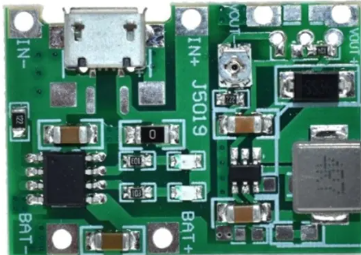
The Charging and Booster Module is a versatile electronic component designed to charge batteries and boost voltage to a desired level. This module is commonly used in portable electronic projects, such as DIY power banks, portable speakers, and other battery-powered devices. It combines the functionality of a battery charger and a DC-DC boost converter, making it an essential component for projects requiring stable and adjustable power supply.
Explore Projects Built with Charging nad Booster Module


Explore Projects Built with Charging nad Booster Module
Technical Specifications
Key Technical Details
| Parameter | Value |
|---|---|
| Input Voltage | 3.7V - 5V |
| Output Voltage | 5V (adjustable) |
| Charging Current | 1A (max) |
| Boost Current | 2A (max) |
| Efficiency | Up to 92% |
| Dimensions | 36mm x 17mm x 7mm |
| Operating Temperature | -40°C to 85°C |
Pin Configuration and Descriptions
| Pin Name | Description |
|---|---|
| IN+ | Positive input voltage (3.7V - 5V) |
| IN- | Negative input voltage (Ground) |
| OUT+ | Positive output voltage (5V, adjustable) |
| OUT- | Negative output voltage (Ground) |
| B+ | Positive terminal for battery connection |
| B- | Negative terminal for battery connection |
Usage Instructions
How to Use the Component in a Circuit
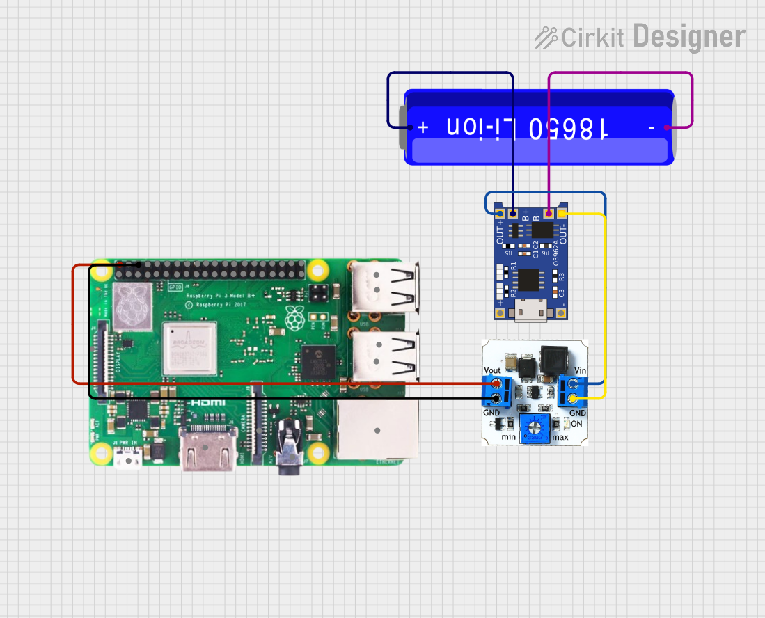
Power Input:
- Connect the power source (e.g., USB, solar panel) to the
IN+andIN-pins. - Ensure the input voltage is within the specified range (3.7V - 5V).
- Connect the power source (e.g., USB, solar panel) to the
Battery Connection:
- Connect the battery to the
B+andB-pins. - Ensure the battery is compatible with the module's charging specifications.
- Connect the battery to the
Output Connection:
- Connect the load (e.g., microcontroller, sensors) to the
OUT+andOUT-pins. - Adjust the output voltage if necessary using the onboard potentiometer.
- Connect the load (e.g., microcontroller, sensors) to the
Important Considerations and Best Practices
- Heat Dissipation: Ensure proper ventilation and heat dissipation, especially when operating at high currents.
- Polarity: Double-check the polarity of all connections to avoid damaging the module.
- Battery Safety: Use batteries with built-in protection circuits to prevent overcharging and over-discharging.
- Load Requirements: Ensure the load does not exceed the maximum output current of the module.
Troubleshooting and FAQs
Common Issues and Solutions
Module Not Powering On:
- Solution: Check the input voltage and ensure it is within the specified range. Verify all connections are secure and correct.
Battery Not Charging:
- Solution: Ensure the battery is properly connected to the
B+andB-pins. Check if the battery is compatible with the module's charging specifications.
- Solution: Ensure the battery is properly connected to the
Output Voltage Not Stable:
- Solution: Adjust the output voltage using the onboard potentiometer. Ensure the load does not exceed the maximum output current.
Module Overheating:
- Solution: Improve ventilation and heat dissipation. Reduce the load current if necessary.
FAQs
Q1: Can I use this module with an Arduino UNO?
- A1: Yes, you can use this module to power an Arduino UNO. Connect the
OUT+andOUT-pins to the Arduino's 5V and GND pins, respectively.
Q2: How do I adjust the output voltage?
- A2: Use the onboard potentiometer to adjust the output voltage. Turn the potentiometer clockwise to increase the voltage and counterclockwise to decrease it.
Q3: What type of batteries can I use with this module?
- A3: You can use lithium-ion or lithium-polymer batteries that are compatible with the module's charging specifications.
Example Code for Arduino UNO
// Example code to read voltage from the Charging and Booster Module
// and display it on the Serial Monitor

const int voltagePin = A0; // Analog pin to read voltage

void setup() {
  Serial.begin(9600); // Initialize serial communication
}

void loop() {
  int sensorValue = analogRead(voltagePin); // Read the analog input
  float voltage = sensorValue * (5.0 / 1023.0); // Convert to voltage
  Serial.print("Voltage: ");
  Serial.print(voltage);
  Serial.println(" V");
  delay(1000); // Wait for 1 second before next reading
}
This example code reads the voltage from the Charging and Booster Module and displays it on the Serial Monitor. Connect the OUT+ pin to the Arduino's A0 pin and the OUT- pin to the Arduino's GND pin.
By following this documentation, users can effectively integrate the Charging and Booster Module into their projects, ensuring reliable and adjustable power supply for various applications.