
How to Use Adafruit 1.2 Inch 8x8 LED Matrix Backpack - White: Examples, Pinouts, and Specs
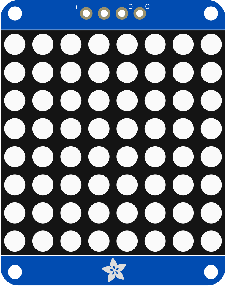
 Design with Adafruit 1.2 Inch 8x8 LED Matrix Backpack - White in Cirkit Designer
Introduction
The Adafruit 1.2 Inch 8x8 LED Matrix Backpack - White (Manufacturer Part ID: 1614) is a compact and versatile LED matrix display module. It features an 8x8 grid of bright white LEDs, making it ideal for creating visual displays, animations, and simple text output in electronic projects. The module is equipped with an I2C interface, simplifying the control of the LED matrix and reducing the number of required pins on your microcontroller.
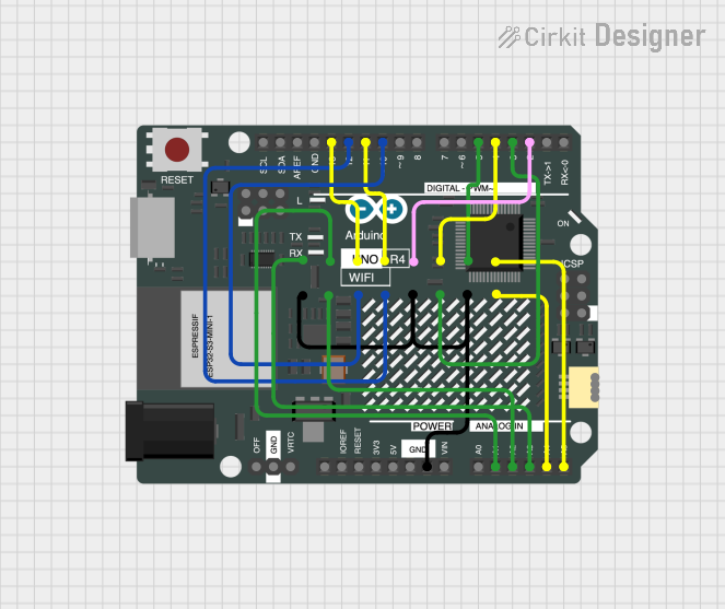
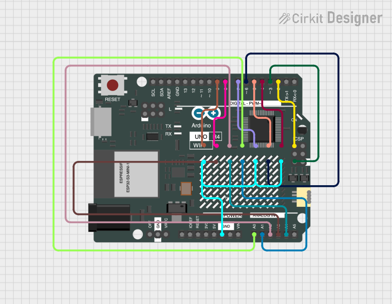
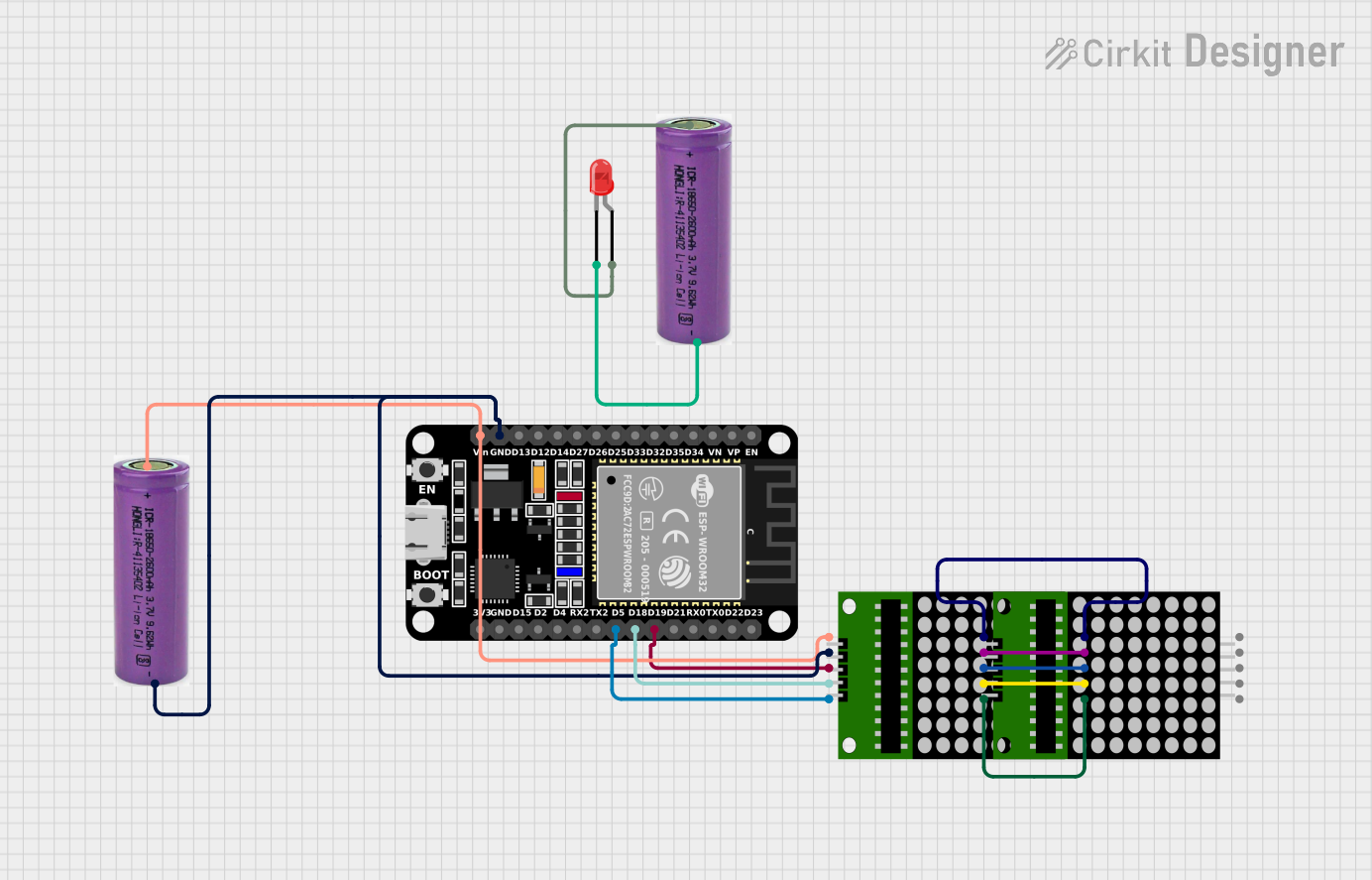
Explore Projects Built with Adafruit 1.2 Inch 8x8 LED Matrix Backpack - White
 Open Project in Cirkit Designer
 Open Project in Cirkit Designer
 Open Project in Cirkit Designer
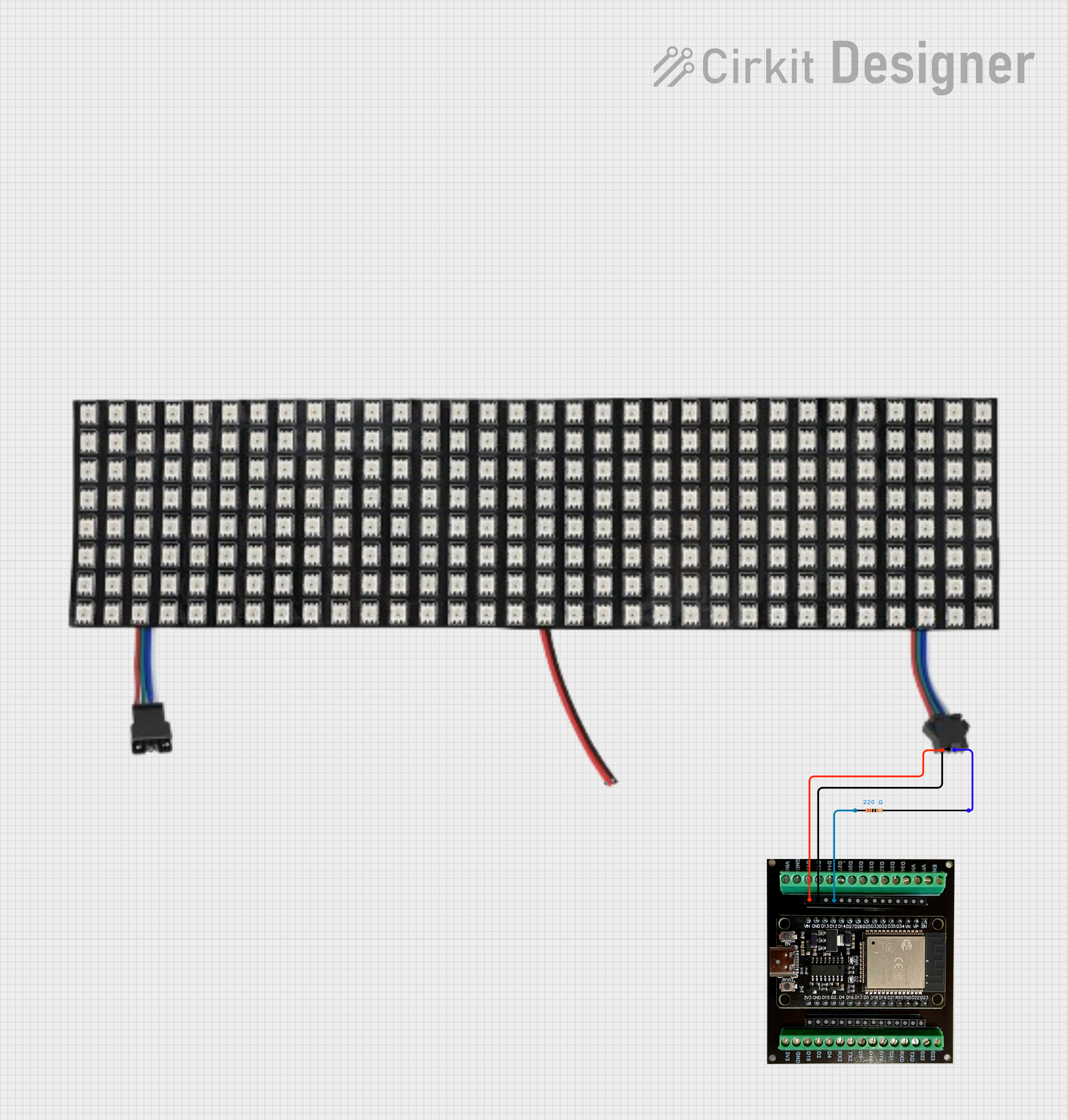 Open Project in Cirkit Designer
Explore Projects Built with Adafruit 1.2 Inch 8x8 LED Matrix Backpack - White
Open Project in Cirkit DesignerOpen Project in Cirkit DesignerOpen Project in Cirkit DesignerOpen Project in Cirkit DesignerCommon Applications and Use Cases
- Digital clocks and timers
- Scrolling text displays
- Visual indicators and status displays
- Animations and simple graphics
- Educational and hobbyist projects
Technical Specifications
Key Technical Details
| Parameter | Value |
|---|---|
| Manufacturer | Adafruit |
| Manufacturer Part ID | 1614 |
| LED Matrix Size | 8x8 (64 LEDs) |
| LED Color | White |
| Matrix Dimensions | 1.2 inches (diagonal) |
| Communication Protocol | I2C |
| Operating Voltage | 5V DC |
| Current Consumption | ~20mA (varies with LED usage) |
| Driver Chip | HT16K33 |
| Mounting | PCB with soldered headers |
Pin Configuration and Descriptions
The module uses a 4-pin header for I2C communication and power. Below is the pinout:
| Pin Name | Description |
|---|---|
| VIN | Power input (5V DC) |
| GND | Ground |
| SDA | I2C data line |
| SCL | I2C clock line |
Usage Instructions
How to Use the Component in a Circuit
Wiring the Module:
- Connect the
VINpin to a 5V power source. - Connect the
GNDpin to the ground of your circuit. - Connect the
SDApin to the I2C data line of your microcontroller. - Connect the
SCLpin to the I2C clock line of your microcontroller.
- Connect the
Installing Required Libraries:
- Download and install the Adafruit HT16K33 library from the Arduino Library Manager. This library simplifies communication with the LED matrix.
Programming the Module:
- Use the Adafruit HT16K33 library to control the LED matrix. Below is an example Arduino sketch to display a simple pattern.
Example Arduino Code
#include <Wire.h>
#include <Adafruit_GFX.h>
#include <Adafruit_LEDBackpack.h>

// Create an instance of the LED matrix object
Adafruit_8x8matrix matrix = Adafruit_8x8matrix();

void setup() {
  // Initialize the LED matrix
  matrix.begin(0x70); // Default I2C address is 0x70

  // Clear the display
  matrix.clear();
  matrix.writeDisplay();

  // Draw a simple pattern (a diagonal line)
  for (int i = 0; i < 8; i++) {
    matrix.drawPixel(i, i, LED_ON); // Turn on LEDs along the diagonal
  }

  // Update the display to show the pattern
  matrix.writeDisplay();
}

void loop() {
  // No actions in the loop for this example
}
Important Considerations and Best Practices
- Ensure the I2C address of the module (default:
0x70) does not conflict with other devices on the same I2C bus. - Use pull-up resistors on the SDA and SCL lines if your microcontroller does not have internal pull-ups enabled.
- Avoid exceeding the module's 5V operating voltage to prevent damage.
- Use a regulated power supply to ensure stable operation.
Troubleshooting and FAQs
Common Issues and Solutions
The LED matrix does not light up:
- Verify all connections, especially power (VIN and GND).
- Ensure the I2C address in your code matches the module's address.
- Check if the required Adafruit HT16K33 library is installed.
Flickering or unstable display:
- Ensure a stable 5V power supply is used.
- Check for loose or poor connections on the I2C lines.
Unable to upload code to Arduino:
- Disconnect the SDA and SCL lines during code upload to avoid interference.
FAQs
Q: Can I change the I2C address of the module?
A: Yes, the module supports address configuration via solder jumpers on the back of the PCB. Refer to the Adafruit documentation for details.
Q: Can I chain multiple LED matrix modules together?
A: Yes, you can connect multiple modules on the same I2C bus by assigning each module a unique I2C address.
Q: What is the maximum viewing angle of the LEDs?
A: The LEDs have a wide viewing angle, typically around 120 degrees.
By following this documentation, you can effectively integrate the Adafruit 1.2 Inch 8x8 LED Matrix Backpack into your projects and create stunning visual displays.