
How to Use shunt 200A: Examples, Pinouts, and Specs
 Design with shunt 200A in Cirkit Designer
Introduction
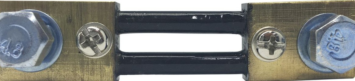
A shunt is a precision, low-resistance component designed to measure current by generating a small voltage drop proportional to the current flowing through it. The Shunt 200A is specifically rated to handle currents up to 200 amperes, making it suitable for high-current applications. It is commonly used in conjunction with ammeters, microcontrollers, or data acquisition systems to monitor current in electrical circuits.
Explore Projects Built with shunt 200A
 Open Project in Cirkit Designer
 Open Project in Cirkit Designer
 Open Project in Cirkit Designer
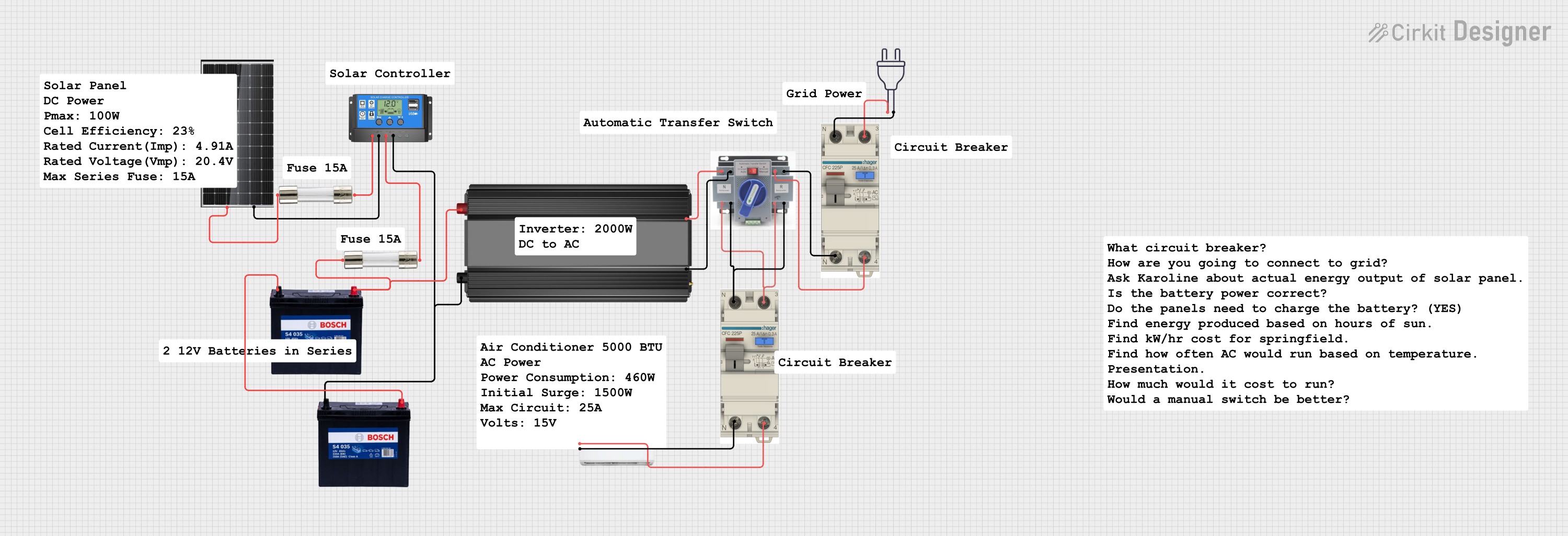 Open Project in Cirkit Designer
Explore Projects Built with shunt 200A
Open Project in Cirkit DesignerOpen Project in Cirkit DesignerOpen Project in Cirkit DesignerOpen Project in Cirkit DesignerCommon Applications and Use Cases
- Battery management systems (BMS) for electric vehicles and renewable energy systems
- High-current power supplies and industrial equipment
- Current monitoring in solar inverters and energy storage systems
- Overcurrent protection and fault detection in electrical circuits
Technical Specifications
The Shunt 200A is designed to provide accurate current measurements while maintaining minimal power loss. Below are its key technical details:
| Parameter | Value |
|---|---|
| Rated Current | 200A |
| Resistance | Typically 50 µΩ (micro-ohms) |
| Voltage Drop | 75 mV at 200A |
| Accuracy | ±0.5% |
| Operating Temperature | -40°C to +85°C |
| Material | Manganin or similar alloy |
| Mounting Style | Screw terminals or bolt-on |
Pin Configuration and Descriptions
The Shunt 200A typically has two main terminals for current flow and two smaller terminals for voltage measurement. Below is the configuration:
| Terminal | Description |
|---|---|
| Current In | Connects to the positive side of the circuit where current enters the shunt. |
| Current Out | Connects to the load or negative side of the circuit where current exits. |
| Sense + | Positive voltage sense terminal for measuring the voltage drop across the shunt. |
| Sense - | Negative voltage sense terminal for measuring the voltage drop across the shunt. |
Usage Instructions
How to Use the Shunt 200A in a Circuit
Placement in the Circuit:
- Place the shunt in series with the load whose current you want to measure.
- Ensure the current flows from the "Current In" terminal to the "Current Out" terminal.
Voltage Measurement:
- Connect the "Sense +" and "Sense -" terminals to a voltmeter, data acquisition system, or microcontroller's analog input pins.
- The voltage drop across the shunt (e.g., 75 mV at 200A) is proportional to the current flowing through it.
Calibration:
- Use the shunt's resistance value (e.g., 50 µΩ) to calculate the current:
[ I = \frac{V}{R} ]
where ( I ) is the current in amperes, ( V ) is the measured voltage in volts, and ( R ) is the shunt resistance in ohms.
- Use the shunt's resistance value (e.g., 50 µΩ) to calculate the current:
Connection to Microcontrollers (e.g., Arduino UNO):
- Use an analog input pin to read the voltage drop across the shunt.
- Scale the analog reading to calculate the current using the shunt's specifications.
Example Arduino Code
// Example code to measure current using a Shunt 200A and Arduino UNO
const int analogPin = A0; // Analog pin connected to Sense + terminal
const float shuntResistance = 0.00005; // Shunt resistance in ohms (50 µΩ)
const float referenceVoltage = 5.0; // Arduino reference voltage (5V for UNO)

void setup() {
  Serial.begin(9600); // Initialize serial communication
}

void loop() {
  int analogValue = analogRead(analogPin); // Read analog value from shunt
  float voltage = (analogValue / 1023.0) * referenceVoltage;
  // Convert analog reading to voltage

  float current = voltage / shuntResistance;
  // Calculate current using Ohm's law

  Serial.print("Current: ");
  Serial.print(current);
  Serial.println(" A"); // Print current in amperes

  delay(1000); // Wait for 1 second before next reading
}
Important Considerations and Best Practices
- Heat Dissipation: Ensure proper ventilation or heat sinking, as the shunt may generate heat at high currents.
- Wiring: Use thick, low-resistance wires for the current terminals to minimize additional resistance.
- Voltage Measurement: Use shielded cables for the sense terminals to avoid noise interference.
- Polarity: Always connect the shunt with the correct polarity to prevent inaccurate readings or damage.
Troubleshooting and FAQs
Common Issues and Solutions
Inaccurate Current Readings:
- Cause: Poor connections or loose terminals.
Solution: Tighten all connections and ensure proper contact. - Cause: Noise interference in the sense lines.
Solution: Use shielded cables and keep sense lines away from high-current wires.
- Cause: Poor connections or loose terminals.
Excessive Heat Generation:
- Cause: Current exceeding the shunt's rated capacity.
Solution: Ensure the current does not exceed 200A. Use a higher-rated shunt if necessary.
- Cause: Current exceeding the shunt's rated capacity.
No Voltage Drop Detected:
- Cause: Incorrect wiring of the sense terminals.
Solution: Verify the polarity and connections of the sense terminals.
- Cause: Incorrect wiring of the sense terminals.
Arduino Reads Zero Current:
- Cause: Incorrect analog pin configuration or damaged shunt.
Solution: Check the analog pin wiring and test the shunt with a multimeter.
- Cause: Incorrect analog pin configuration or damaged shunt.
FAQs
Q1: Can I use the Shunt 200A for AC current measurement?
A1: The Shunt 200A is primarily designed for DC current measurement. For AC applications, additional circuitry (e.g., rectifiers) may be required.
Q2: What happens if the current exceeds 200A?
A2: Exceeding the rated current can cause overheating, damage to the shunt, or inaccurate readings. Always use a shunt rated for the maximum expected current.
Q3: Can I use multiple shunts in parallel?
A3: Yes, but ensure the shunts are identical in resistance and properly balanced to share the current equally.
Q4: How do I protect the shunt from overcurrent?
A4: Use a fuse or circuit breaker rated slightly above the shunt's maximum current capacity to prevent damage.