
How to Use ESC 90A: Examples, Pinouts, and Specs
 Design with ESC 90A in Cirkit Designer
Introduction
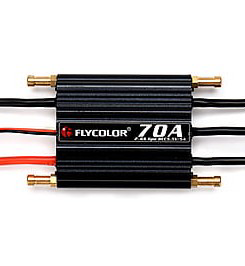
The FLYCOLOR 90A Electronic Speed Controller (ESC) is a high-performance component designed to regulate and control the speed of brushless motors. With a current rating of 90 Amperes, this ESC is ideal for applications requiring high power and precision, such as drones, remote-controlled (RC) vehicles, boats, and other hobbyist or industrial projects. Its robust design ensures reliable operation under demanding conditions, making it a popular choice for enthusiasts and professionals alike.
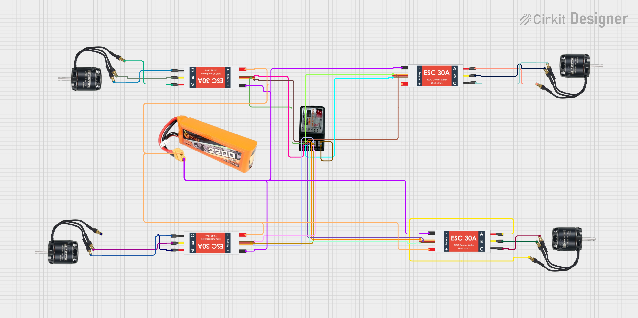
Explore Projects Built with ESC 90A
 Open Project in Cirkit Designer
 Open Project in Cirkit Designer
 Open Project in Cirkit Designer
 Open Project in Cirkit Designer
Explore Projects Built with ESC 90A
Open Project in Cirkit DesignerOpen Project in Cirkit DesignerOpen Project in Cirkit DesignerOpen Project in Cirkit DesignerCommon Applications
- Multirotor drones (quadcopters, hexacopters, etc.)
- RC cars, trucks, and buggies
- RC boats and watercraft
- Robotics and automation projects
- Electric-powered model aircraft
Technical Specifications
The FLYCOLOR 90A ESC is engineered to deliver consistent performance while maintaining safety and efficiency. Below are the key technical details:
General Specifications
| Parameter | Value |
|---|---|
| Manufacturer | FLYCOLOR |
| Part ID | 90A |
| Continuous Current | 90 Amperes |
| Peak Current | 120 Amperes (for 10 seconds) |
| Input Voltage Range | 2S–6S LiPo (7.4V–22.2V) |
| Motor Compatibility | Brushless motors (sensorless) |
| BEC Output | 5V/3A (Linear mode) |
| Weight | ~65 grams |
| Dimensions | 70mm x 35mm x 15mm |
| Operating Temperature | -10°C to 85°C |
Pin Configuration and Descriptions
The ESC has three main connection points: motor wires, power input, and signal input. Below is a detailed description of each:
Motor Wires (Output)
| Wire Color | Description |
|---|---|
| Yellow | Connect to one motor phase |
| Blue | Connect to another motor phase |
| Orange | Connect to the third motor phase |
Power Input
| Wire Color | Description |
|---|---|
| Red | Positive terminal (+) for power |
| Black | Negative terminal (-) for power |
Signal Input
| Wire Color | Description |
|---|---|
| White | PWM signal input from receiver |
| Red | Positive power for receiver (5V) |
| Black | Ground for receiver |
Usage Instructions
How to Use the ESC in a Circuit
Connect the Motor Wires: Attach the three motor wires (yellow, blue, orange) to the corresponding terminals of the brushless motor. The order of connection determines the motor's rotation direction. If the motor spins in the wrong direction, swap any two wires.
Connect the Power Input:
- Connect the red wire to the positive terminal of the battery.
- Connect the black wire to the negative terminal of the battery.
- Ensure the battery voltage is within the ESC's supported range (2S–6S LiPo).
Connect the Signal Input:
- Plug the white wire into the PWM signal pin of your receiver or microcontroller (e.g., Arduino).
- Connect the red and black wires to power and ground, respectively, for the receiver.
Calibrate the ESC:
- Power on the ESC while holding the throttle at maximum.
- Wait for the calibration tones, then move the throttle to the minimum position.
- The ESC will emit confirmation tones, indicating successful calibration.
Test the Setup:
- Gradually increase the throttle to ensure the motor responds correctly.
- Monitor the ESC and motor for any unusual behavior, such as overheating or erratic operation.
Important Considerations and Best Practices
- Cooling: Ensure adequate airflow around the ESC to prevent overheating during operation.
- Battery Compatibility: Use only LiPo batteries within the specified voltage range (2S–6S).
- Signal Input: Use a PWM signal with a frequency between 50Hz and 500Hz for optimal performance.
- Safety: Always disconnect the battery when making adjustments to the wiring or motor connections.
Example Code for Arduino UNO
Below is an example of how to control the ESC 90A using an Arduino UNO:
#include <Servo.h> // Include the Servo library for PWM signal generation

Servo esc; // Create a Servo object to control the ESC

void setup() {
  esc.attach(9); // Attach the ESC signal wire to pin 9
  esc.writeMicroseconds(1000); // Set initial throttle to minimum (1000 µs)
  delay(2000); // Wait for the ESC to initialize
}

void loop() {
  esc.writeMicroseconds(1500); // Set throttle to mid-range (1500 µs)
  delay(5000); // Run motor at mid-speed for 5 seconds

  esc.writeMicroseconds(1000); // Set throttle to minimum (stop motor)
  delay(5000); // Wait for 5 seconds before repeating
}
Note: Adjust the throttle values (1000 to 2000 microseconds) based on your motor's requirements. Always test in a safe environment.
Troubleshooting and FAQs
Common Issues and Solutions
Motor Does Not Spin:
- Verify all connections (motor wires, power input, and signal input).
- Ensure the battery is charged and within the ESC's voltage range.
- Check the PWM signal from the receiver or microcontroller.
Motor Spins in the Wrong Direction:
- Swap any two motor wires to reverse the rotation direction.
ESC Overheats:
- Ensure proper cooling and airflow around the ESC.
- Verify that the motor and battery are within the ESC's specifications.
Calibration Fails:
- Ensure the throttle range on your transmitter or microcontroller is correctly configured.
- Repeat the calibration process carefully.
FAQs
Q: Can I use this ESC with a brushed motor?
A: No, the FLYCOLOR 90A ESC is designed specifically for sensorless brushless motors.
Q: What happens if I exceed the ESC's voltage rating?
A: Exceeding the voltage rating can damage the ESC and void the warranty. Always use a battery within the specified range (2S–6S LiPo).
Q: Can I use this ESC for a fixed-wing aircraft?
A: Yes, the ESC is suitable for fixed-wing aircraft as long as the motor and battery are compatible.
Q: How do I update the firmware on this ESC?
A: The FLYCOLOR 90A ESC does not support firmware updates. Ensure you purchase the correct version for your application.
By following this documentation, you can effectively integrate and operate the FLYCOLOR 90A ESC in your projects.