Cirkit Designer Logo
Cirkit Designer
Your all-in-one circuit design IDE
Home / 
Component Documentation

How to Use hlk-ld2412: Examples, Pinouts, and Specs

Image of hlk-ld2412
Cirkit Designer LogoDesign with hlk-ld2412 in Cirkit Designer

Introduction

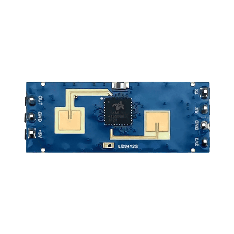
The HLK-LD2412 is a compact, isolated DC-DC converter module manufactured by Hi-Link. It is designed to convert a 24V DC input into a stable and regulated 12V DC output. This module is highly efficient, reliable, and suitable for powering a wide range of electronic devices and circuits. Its small form factor and robust design make it ideal for industrial, automotive, and embedded system applications.

Explore Projects Built with hlk-ld2412

Use Cirkit Designer to design, explore, and prototype these projects online. Some projects support real-time simulation. Click "Open Project" to start designing instantly!
Cellular-Enabled IoT Device with Real-Time Clock and Power Management
Image of LRCM PHASE 2 BASIC: A project utilizing hlk-ld2412 in a practical application
This circuit features a LilyGo-SIM7000G module for cellular communication and GPS functionality, interfaced with an RTC DS3231 for real-time clock capabilities. It includes voltage sensing through two voltage sensor modules, and uses an 8-channel opto-coupler for isolating different parts of the circuit. Power management is handled by a buck converter connected to a DC power source and batteries, with a fuse for protection and a rocker switch for on/off control. Additionally, there's an LED for indication purposes.
Cirkit Designer LogoOpen Project in Cirkit Designer
NFC-Enabled Access Control System with Time Logging
Image of doorlock: A project utilizing hlk-ld2412 in a practical application
This circuit is designed for access control with time tracking capabilities. It features an NFC/RFID reader for authentication, an RTC module (DS3231) for real-time clock functionality, and an OLED display for user interaction. A 12V relay controls a magnetic lock, which is activated upon successful NFC/RFID authentication, and a button switch is likely used for manual operation or input. The T8_S3 microcontroller serves as the central processing unit, interfacing with the NFC/RFID reader, RTC, OLED, and relay to manage the access control logic.
Cirkit Designer LogoOpen Project in Cirkit Designer
NFC-Enabled Access Control System with Real-Time Clock and OLED Display
Image of doorlock: A project utilizing hlk-ld2412 in a practical application
This circuit is designed as an access control system with time-tracking capabilities. It uses an NFC/RFID reader for authentication, a real-time clock for time-stamping events, and an OLED display for user interface, all controlled by a T8_S3 microcontroller. A relay module actuates a magnetic lock, and a button switch provides additional user input, with a switching power supply delivering the necessary voltages.
Cirkit Designer LogoOpen Project in Cirkit Designer
Bluetooth-Controlled Robotic Car with L293D Motor Driver and LED Indicators
Image of Bluetooth Car Diagram: A project utilizing hlk-ld2412 in a practical application
This circuit is a motor control system that uses an L293D driver shield to control four hobby gearmotors, with each motor connected to an LED and a resistor for status indication. The system is powered by a 2x 18650 battery pack and includes an HC-05 Bluetooth module for wireless communication.
Cirkit Designer LogoOpen Project in Cirkit Designer

Explore Projects Built with hlk-ld2412

Use Cirkit Designer to design, explore, and prototype these projects online. Some projects support real-time simulation. Click "Open Project" to start designing instantly!
Image of LRCM PHASE 2 BASIC: A project utilizing hlk-ld2412 in a practical application
Cellular-Enabled IoT Device with Real-Time Clock and Power Management
This circuit features a LilyGo-SIM7000G module for cellular communication and GPS functionality, interfaced with an RTC DS3231 for real-time clock capabilities. It includes voltage sensing through two voltage sensor modules, and uses an 8-channel opto-coupler for isolating different parts of the circuit. Power management is handled by a buck converter connected to a DC power source and batteries, with a fuse for protection and a rocker switch for on/off control. Additionally, there's an LED for indication purposes.
Cirkit Designer LogoOpen Project in Cirkit Designer
Image of doorlock: A project utilizing hlk-ld2412 in a practical application
NFC-Enabled Access Control System with Time Logging
This circuit is designed for access control with time tracking capabilities. It features an NFC/RFID reader for authentication, an RTC module (DS3231) for real-time clock functionality, and an OLED display for user interaction. A 12V relay controls a magnetic lock, which is activated upon successful NFC/RFID authentication, and a button switch is likely used for manual operation or input. The T8_S3 microcontroller serves as the central processing unit, interfacing with the NFC/RFID reader, RTC, OLED, and relay to manage the access control logic.
Cirkit Designer LogoOpen Project in Cirkit Designer
Image of doorlock: A project utilizing hlk-ld2412 in a practical application
NFC-Enabled Access Control System with Real-Time Clock and OLED Display
This circuit is designed as an access control system with time-tracking capabilities. It uses an NFC/RFID reader for authentication, a real-time clock for time-stamping events, and an OLED display for user interface, all controlled by a T8_S3 microcontroller. A relay module actuates a magnetic lock, and a button switch provides additional user input, with a switching power supply delivering the necessary voltages.
Cirkit Designer LogoOpen Project in Cirkit Designer
Image of Bluetooth Car Diagram: A project utilizing hlk-ld2412 in a practical application
Bluetooth-Controlled Robotic Car with L293D Motor Driver and LED Indicators
This circuit is a motor control system that uses an L293D driver shield to control four hobby gearmotors, with each motor connected to an LED and a resistor for status indication. The system is powered by a 2x 18650 battery pack and includes an HC-05 Bluetooth module for wireless communication.
Cirkit Designer LogoOpen Project in Cirkit Designer

Common Applications

  • Powering microcontrollers, sensors, and other low-power devices
  • Industrial automation systems
  • Automotive electronics
  • Embedded systems and IoT devices
  • Battery-powered equipment requiring voltage regulation

Technical Specifications

The HLK-LD2412 module is designed to meet the needs of various applications with the following key specifications:

Parameter Value
Input Voltage Range 18V DC to 36V DC
Output Voltage 12V DC
Output Current 0A to 1A
Output Power 12W (maximum)
Efficiency Up to 85%
Isolation Voltage 1500V DC
Operating Temperature -25°C to +70°C
Storage Temperature -40°C to +85°C
Dimensions 50mm x 25mm x 15mm
Weight Approximately 20g

Pin Configuration and Descriptions

The HLK-LD2412 module has four pins for input and output connections. The pinout is as follows:

Pin Number Pin Name Description
1 VIN+ Positive input voltage (18V to 36V DC)
2 VIN- Negative input voltage (Ground)
3 VOUT+ Positive regulated output voltage (12V)
4 VOUT- Negative regulated output voltage (Ground)

Usage Instructions

How to Use the HLK-LD2412 in a Circuit

  1. Input Voltage Connection: Connect the VIN+ and VIN- pins to a 24V DC power source. Ensure the input voltage is within the specified range (18V to 36V DC).
  2. Output Voltage Connection: Connect the VOUT+ and VOUT- pins to the load or circuit requiring a 12V DC supply.
  3. Decoupling Capacitors: For optimal performance, place decoupling capacitors (e.g., 10µF and 0.1µF) close to the input and output pins to reduce noise and improve stability.
  4. Mounting: Secure the module on a PCB or enclosure using appropriate mounting hardware. Ensure proper ventilation to prevent overheating.

Important Considerations and Best Practices

  • Input Voltage Range: Do not exceed the input voltage range (18V to 36V DC) to avoid damaging the module.
  • Load Requirements: Ensure the connected load does not exceed the maximum output current of 1A.
  • Heat Dissipation: If the module operates near its maximum power rating, consider adding a heatsink or improving airflow to manage heat dissipation.
  • Isolation: The module provides 1500V DC isolation, making it suitable for applications requiring electrical isolation between input and output.

Example: Using HLK-LD2412 with an Arduino UNO

The HLK-LD2412 can be used to power an Arduino UNO by converting a 24V DC input to a regulated 12V DC output. Below is an example circuit and Arduino code:

Circuit Diagram

  1. Connect a 24V DC power source to the VIN+ and VIN- pins of the HLK-LD2412.
  2. Connect the VOUT+ pin to the Arduino UNO's VIN pin.
  3. Connect the VOUT- pin to the Arduino UNO's GND pin.

Arduino Code Example

// Example code to blink an LED connected to pin 13 of the Arduino UNO
// Ensure the Arduino is powered via the HLK-LD2412 module

void setup() {
  pinMode(13, OUTPUT); // Set pin 13 as an output
}

void loop() {
  digitalWrite(13, HIGH); // Turn the LED on
  delay(1000);            // Wait for 1 second
  digitalWrite(13, LOW);  // Turn the LED off
  delay(1000);            // Wait for 1 second
}

Troubleshooting and FAQs

Common Issues and Solutions

  1. No Output Voltage

    • Cause: Input voltage is outside the specified range.
    • Solution: Verify that the input voltage is between 18V and 36V DC.
  2. Overheating

    • Cause: Module is operating near its maximum power rating without proper ventilation.
    • Solution: Improve airflow or add a heatsink to dissipate heat.
  3. Output Voltage Fluctuations

    • Cause: Insufficient decoupling capacitors or unstable input voltage.
    • Solution: Add decoupling capacitors (e.g., 10µF and 0.1µF) near the input and output pins.
  4. Module Not Powering the Load

    • Cause: Load exceeds the maximum output current of 1A.
    • Solution: Reduce the load to within the module's specifications.

FAQs

  1. Can the HLK-LD2412 be used with a 12V input?

    • No, the input voltage must be between 18V and 36V DC for proper operation.
  2. Is the module protected against reverse polarity?

    • No, the module does not have built-in reverse polarity protection. Ensure correct polarity when connecting the input voltage.
  3. Can the module be used in outdoor applications?

    • The HLK-LD2412 is not weatherproof. If used outdoors, it must be enclosed in a weatherproof housing.
  4. What is the maximum cable length for input and output connections?

    • Keep cable lengths as short as possible to minimize voltage drops and noise. Use appropriately rated wires for the current and voltage.

By following this documentation, users can effectively integrate the HLK-LD2412 into their projects and ensure reliable performance.