
How to Use Arduino 101: Examples, Pinouts, and Specs
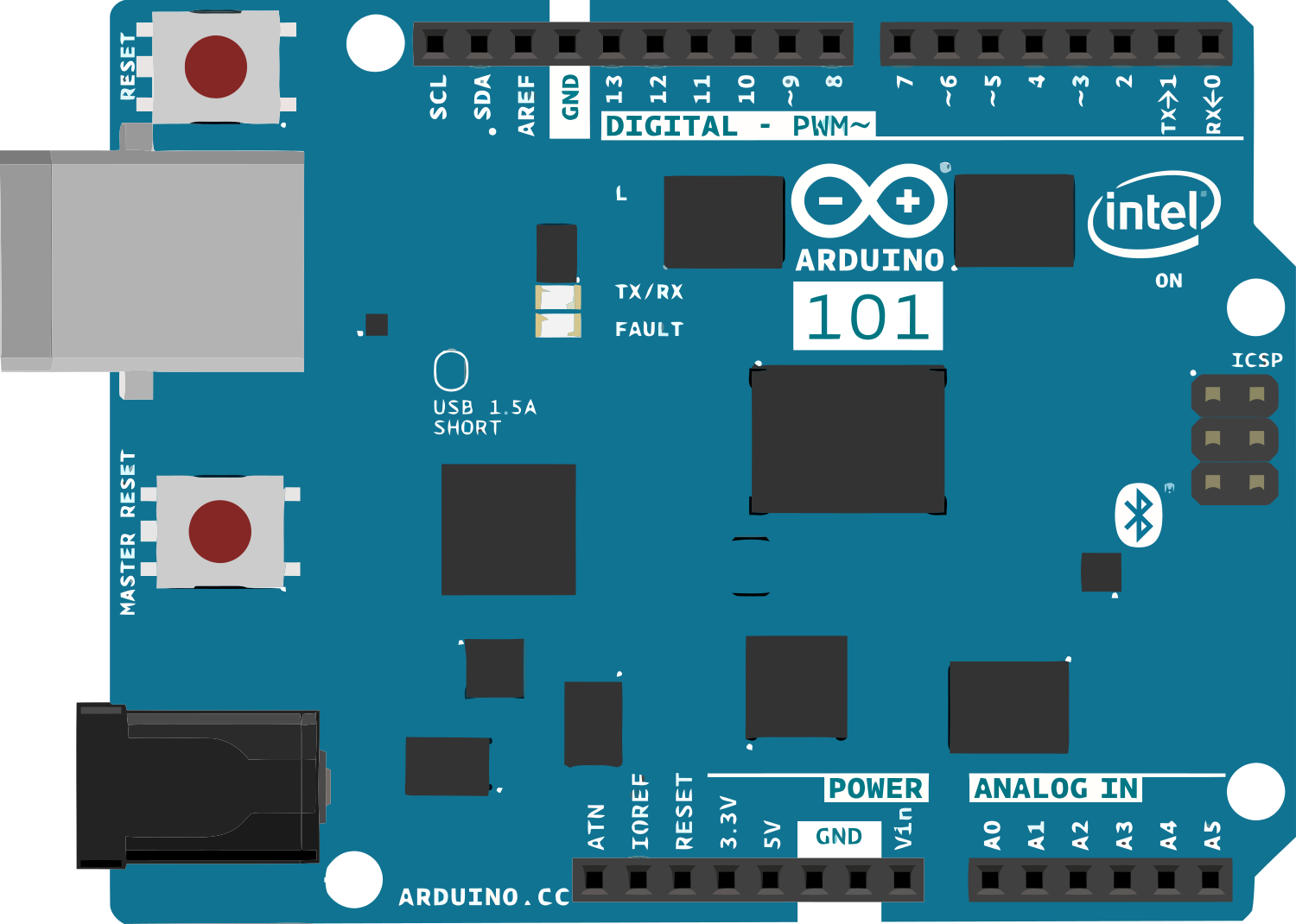
 Design with Arduino 101 in Cirkit Designer
Introduction
The Arduino 101 is a microcontroller board based on the Intel Curie module. It combines the simplicity of Arduino with advanced features such as built-in Bluetooth Low Energy (BLE) capabilities and a 6-axis accelerometer/gyroscope. This board is ideal for projects requiring wireless communication, motion sensing, and real-time control. Its versatility makes it suitable for applications in IoT, wearable devices, robotics, and educational projects.
Explore Projects Built with Arduino 101
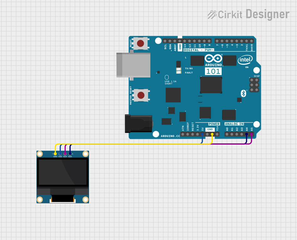 Open Project in Cirkit Designer
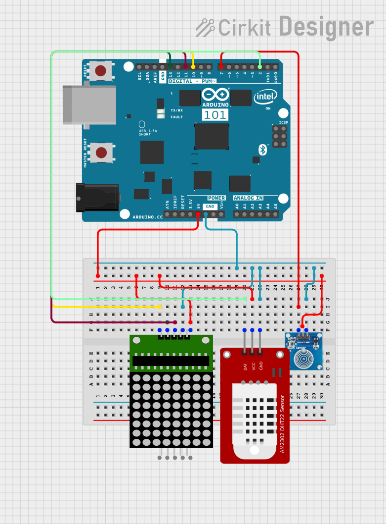 Open Project in Cirkit Designer
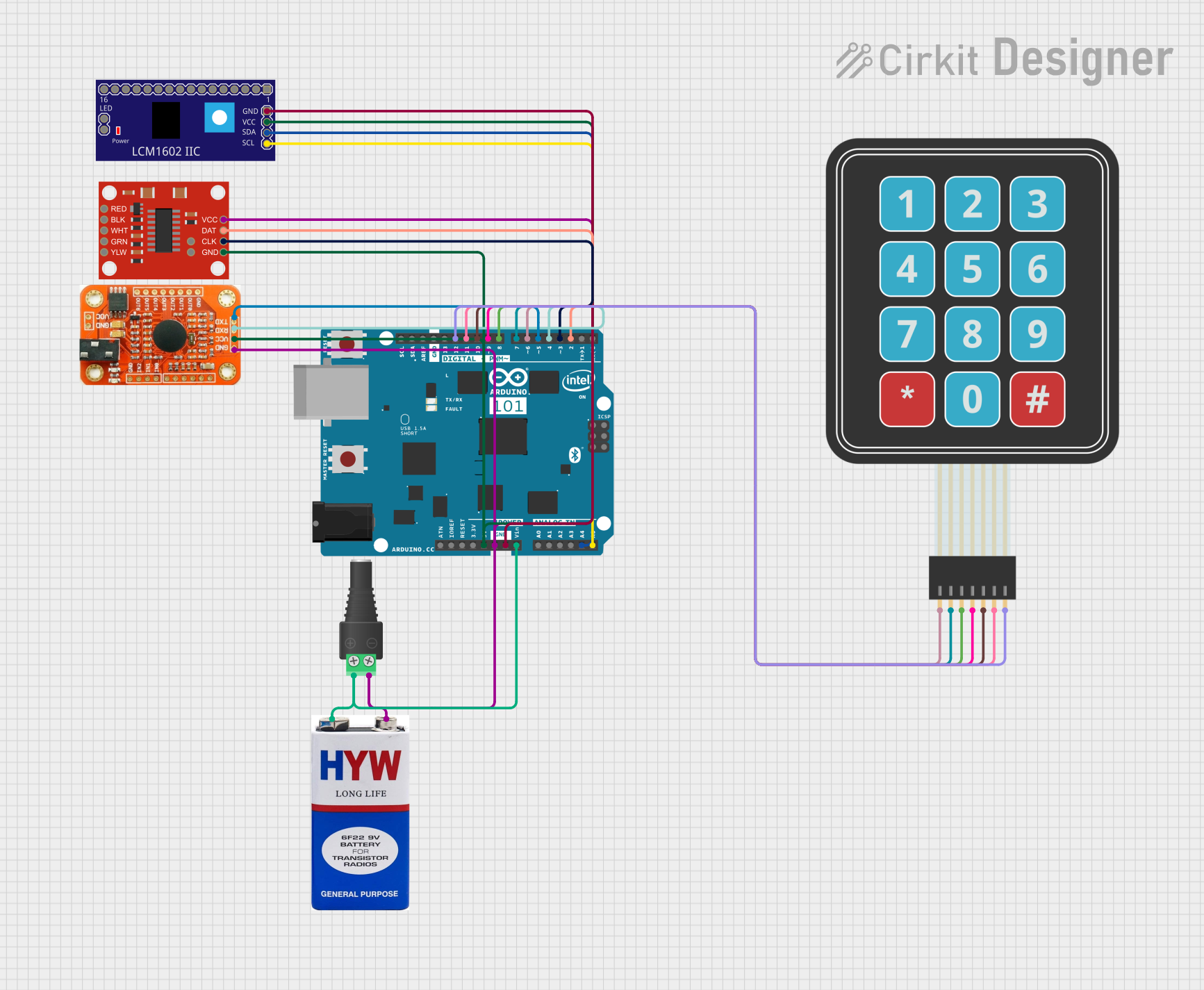 Open Project in Cirkit Designer
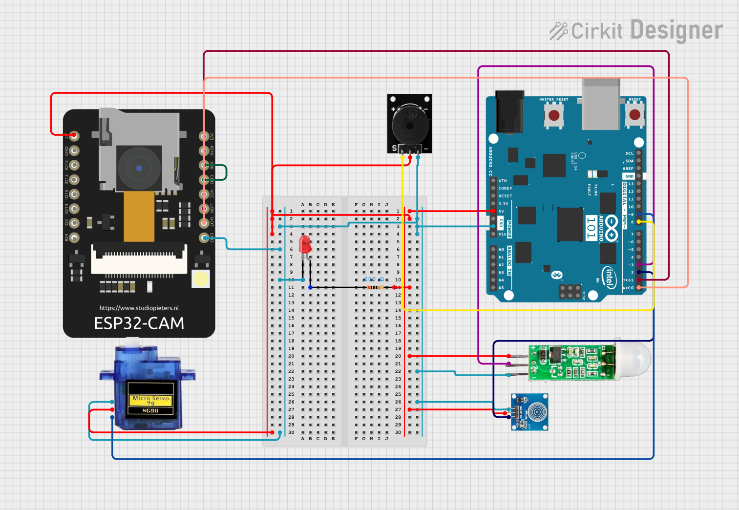 Open Project in Cirkit Designer
Explore Projects Built with Arduino 101
Open Project in Cirkit DesignerOpen Project in Cirkit DesignerOpen Project in Cirkit DesignerOpen Project in Cirkit DesignerCommon Applications
- IoT (Internet of Things) devices
- Wearable technology
- Motion tracking and gesture recognition
- Robotics and automation
- Educational tools for learning embedded systems and programming
Technical Specifications
Key Technical Details
| Specification | Value |
|---|---|
| Microcontroller | Intel Curie module |
| Operating Voltage | 3.3V |
| Input Voltage (recommended) | 7-12V |
| Input Voltage (limit) | 6-20V |
| Digital I/O Pins | 14 (4 PWM outputs) |
| Analog Input Pins | 6 |
| DC Current per I/O Pin | 20 mA |
| Flash Memory | 196 KB (96 KB for user applications) |
| SRAM | 24 KB |
| Clock Speed | 32 MHz |
| Bluetooth | Bluetooth Low Energy (BLE) |
| Sensors | 6-axis accelerometer/gyroscope |
| USB Connector | Micro USB |
Pin Configuration and Descriptions
| Pin Number/Name | Type | Description |
|---|---|---|
| 0-13 | Digital I/O | General-purpose digital input/output pins. |
| A0-A5 | Analog Input | Analog input pins for reading sensor data. |
| GND | Power | Ground pin. |
| 3.3V | Power | 3.3V output for powering external devices. |
| 5V | Power | 5V output for powering external devices. |
| VIN | Power | Input voltage to the board when using an |
| external power source (7-12V recommended). | ||
| TX (Pin 1) | UART | Transmit pin for serial communication. |
| RX (Pin 0) | UART | Receive pin for serial communication. |
| PWM Pins | Digital I/O | Pins 3, 5, 6, 9 (support PWM output). |
| I2C (A4, A5) | Communication | I2C communication pins (SDA, SCL). |
| SPI (10, 11, 12, 13) | Communication | SPI communication pins. |
Usage Instructions
How to Use the Arduino 101 in a Circuit
Powering the Board:
- Connect the Arduino 101 to your computer via the Micro USB cable for programming and power.
- Alternatively, use an external power supply (7-12V) connected to the VIN pin or the DC power jack.
Programming the Board:
- Install the Arduino IDE on your computer.
- Add the Intel Curie Boards package via the Arduino Boards Manager.
- Select "Arduino/Genuino 101" from the Tools > Board menu.
- Write your code and upload it to the board using the USB connection.
Using Bluetooth:
- The Arduino 101 features built-in BLE. Use the CurieBLE library to create BLE peripherals or central devices.
- Pair the board with a smartphone or other BLE-enabled device for wireless communication.
Using the Accelerometer/Gyroscope:
- Use the CurieIMU library to access the 6-axis accelerometer/gyroscope.
- This can be used for motion sensing, gesture recognition, or orientation tracking.
Example Code: Reading Accelerometer Data
#include <CurieIMU.h> // Include the CurieIMU library

void setup() {
  Serial.begin(9600); // Initialize serial communication
  while (!Serial);    // Wait for the serial port to open

  // Initialize the IMU
  if (!CurieIMU.begin()) {
    Serial.println("Failed to initialize IMU!");
    while (1); // Halt the program if initialization fails
  }

  Serial.println("IMU initialized successfully!");

  // Set accelerometer range to ±2g
  CurieIMU.setAccelerometerRange(2);
}

void loop() {
  int ax, ay, az;

  // Read accelerometer data
  CurieIMU.readAccelerometer(ax, ay, az);

  // Print the accelerometer values
  Serial.print("Accelerometer: ");
  Serial.print("X = "); Serial.print(ax);
  Serial.print(", Y = "); Serial.print(ay);
  Serial.print(", Z = "); Serial.println(az);

  delay(500); // Wait 500ms before the next reading
}
Important Considerations
- Voltage Levels: The Arduino 101 operates at 3.3V logic levels. Ensure that any external components connected to the I/O pins are compatible with 3.3V.
- Power Supply: Avoid exceeding the recommended input voltage range (7-12V) to prevent damage to the board.
- BLE Range: The effective range of the BLE module depends on environmental factors. Ensure minimal interference for optimal performance.
- Library Compatibility: Use libraries specifically designed for the Intel Curie module, such as CurieBLE and CurieIMU.
Troubleshooting and FAQs
Common Issues and Solutions
Problem: The board is not recognized by the Arduino IDE.
Solution:- Ensure the correct drivers are installed.
- Check that the Intel Curie Boards package is installed in the Boards Manager.
- Try a different USB cable or port.
Problem: BLE connection is unstable or not working.
Solution:- Verify that the BLE device is within range.
- Ensure the CurieBLE library is used correctly in your code.
- Restart the board and the BLE device to reset the connection.
Problem: The accelerometer/gyroscope is not providing data.
Solution:- Confirm that the CurieIMU library is included and initialized in your code.
- Check the wiring and connections if using external sensors.
- Ensure the board is not physically damaged.
Problem: The board overheats during operation.
Solution:- Verify that the input voltage does not exceed the recommended range.
- Avoid drawing excessive current from the I/O pins.
FAQs
Can I use the Arduino 101 with a 5V sensor?
Yes, but you will need a level shifter to convert the 5V signals to 3.3V.Is the Arduino 101 compatible with standard Arduino shields?
Yes, as long as the shields are compatible with 3.3V logic levels.Can I use the Arduino 101 for battery-powered projects?
Yes, you can power the board using a battery connected to the VIN pin or the DC power jack.What is the maximum BLE range of the Arduino 101?
The BLE range is typically around 10-30 meters, depending on environmental conditions.
This concludes the documentation for the Arduino 101. Happy building!