How to Use MP6500: Examples, Pinouts, and Specs
Introduction
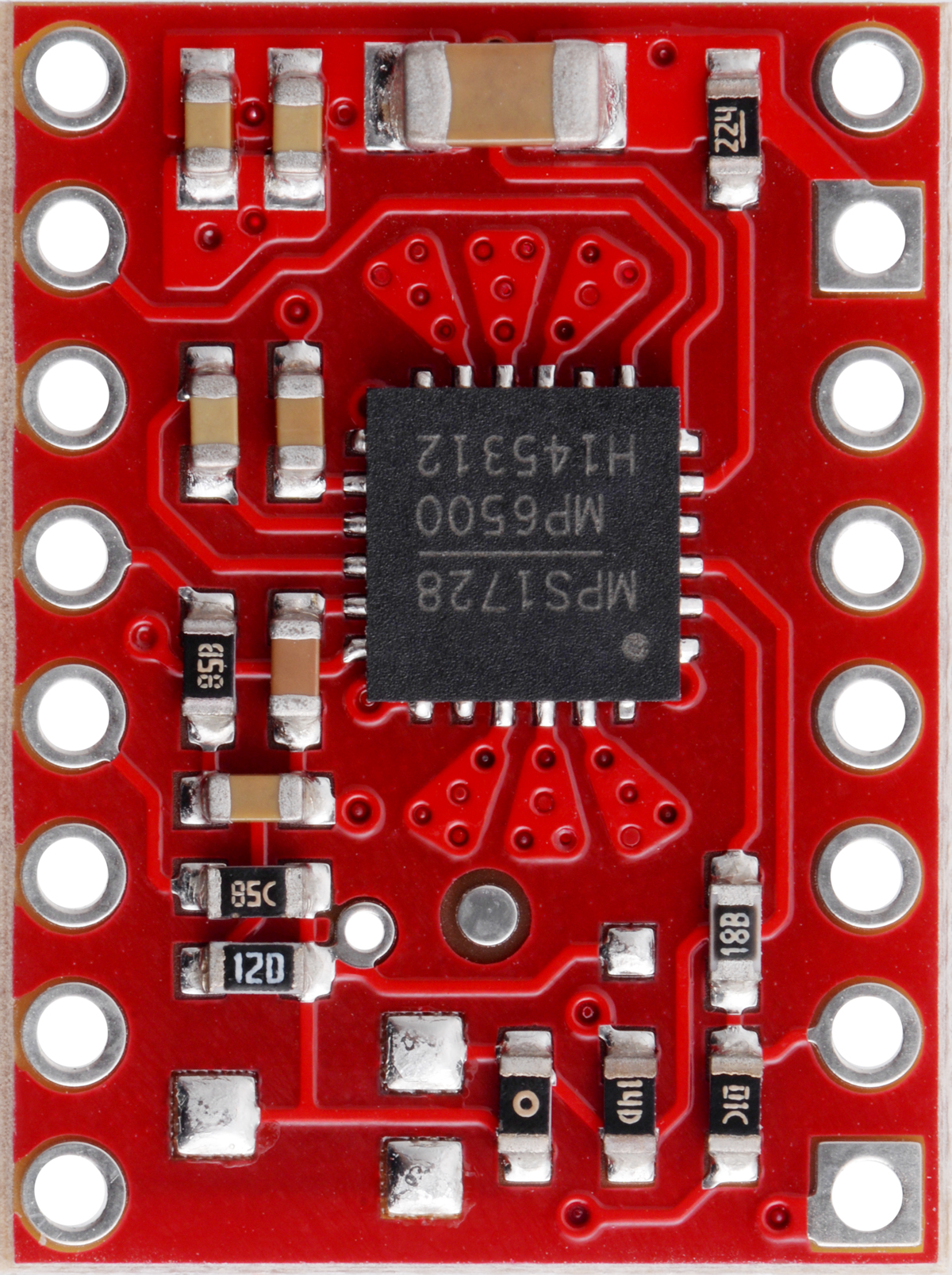
The MP6500 is a high-performance stepper motor driver manufactured by Pololu. It is designed to provide precise control of stepper motors, making it an ideal choice for applications requiring smooth and accurate motion. The MP6500 supports adjustable current control, microstepping capabilities, and includes built-in protection features such as overcurrent, overtemperature, and undervoltage lockout. These features make it a versatile and reliable component for robotics, 3D printing, CNC machines, and other automation systems.
Explore Projects Built with MP6500

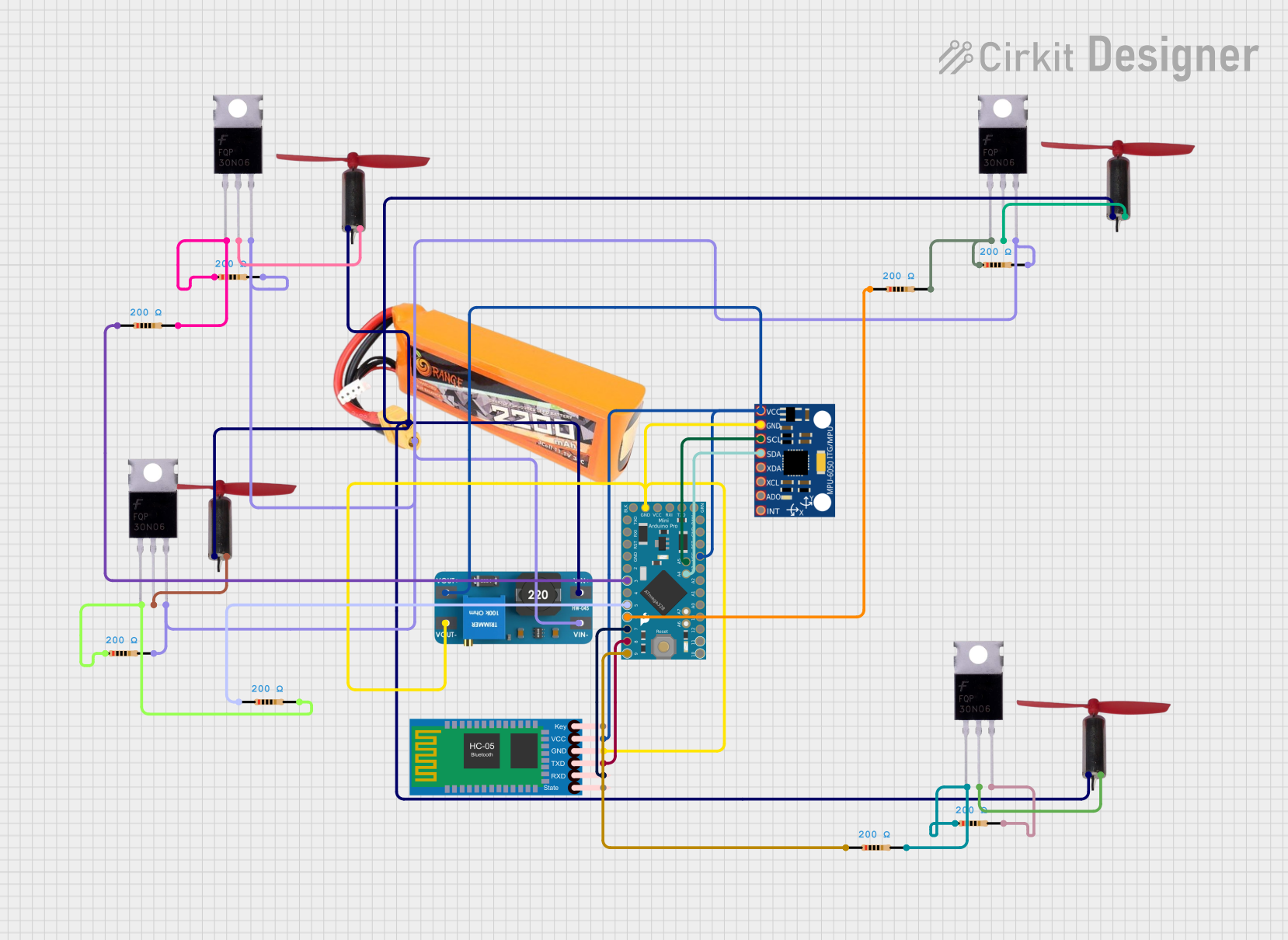
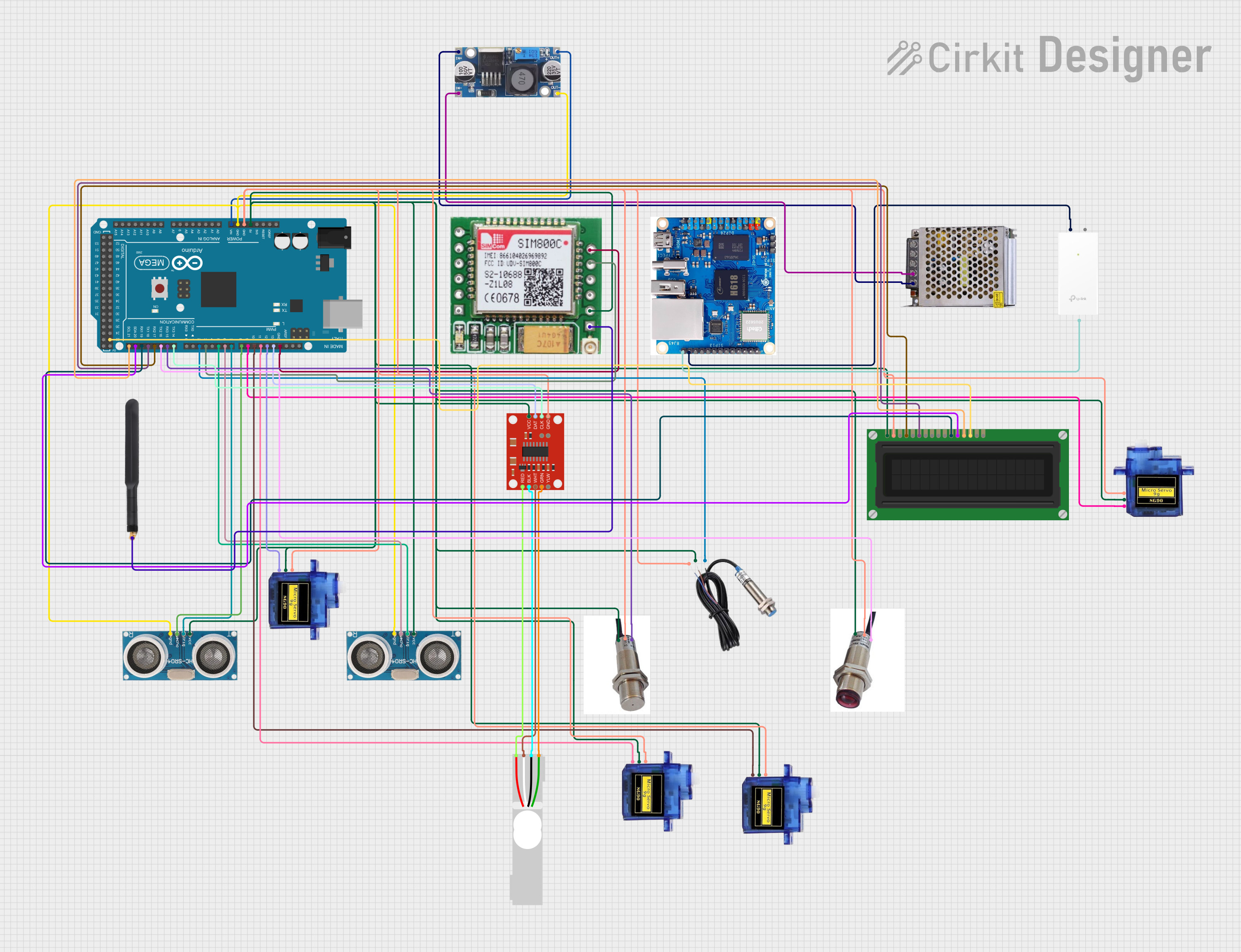
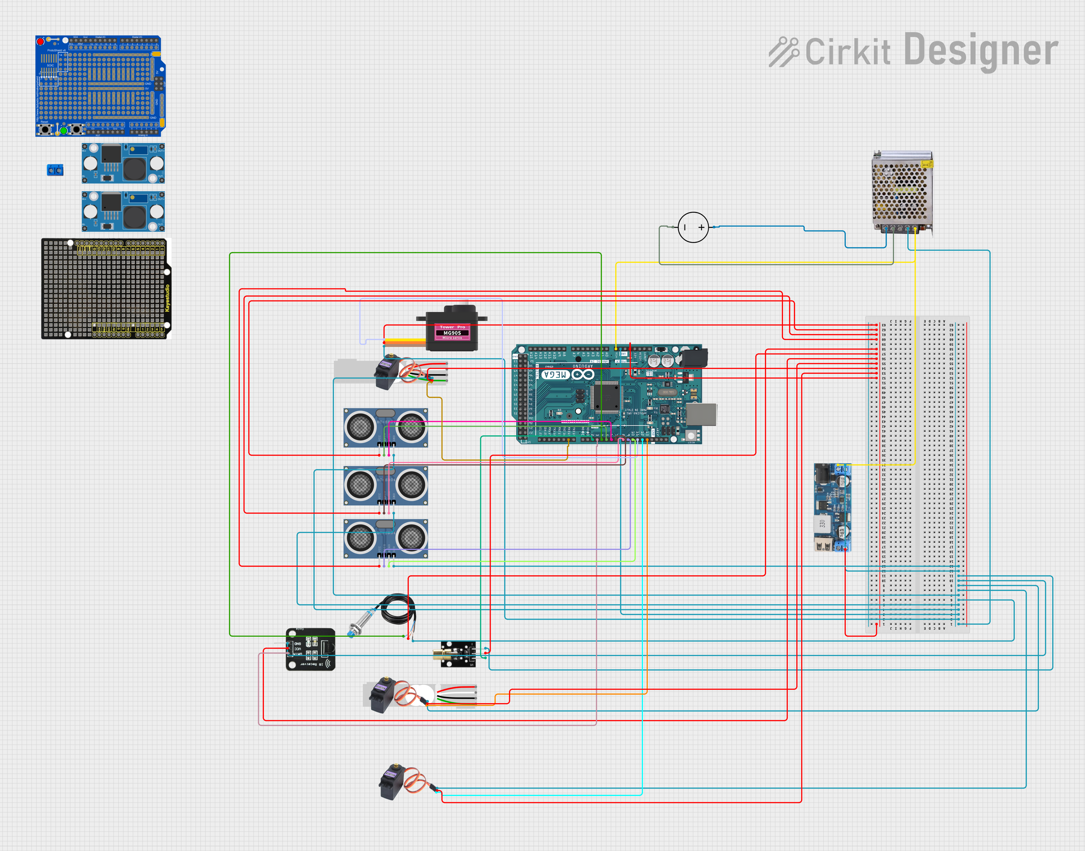
Explore Projects Built with MP6500
Common Applications
- Robotics and automation systems
- 3D printers
- CNC machines
- Camera sliders and gimbals
- Precision motion control systems
Technical Specifications
The MP6500 stepper motor driver has the following key technical specifications:
| Parameter | Value |
|---|---|
| Operating Voltage Range | 4.5 V to 35 V |
| Maximum Output Current | 1.5 A continuous per phase (up to 2.5 A peak with sufficient cooling) |
| Microstepping Modes | Full-step, half-step, 1/4-step, 1/8-step, 1/16-step |
| Logic Voltage Range | 2.5 V to 5.5 V |
| Current Control | Adjustable via potentiometer (requires external current-sense resistors) |
| Built-in Protections | Overcurrent, overtemperature, undervoltage lockout |
| Dimensions | 15.2 mm × 20.3 mm × 3.8 mm |
Pin Configuration and Descriptions
The MP6500 driver module has the following pinout:
| Pin Name | Description |
|---|---|
| VM | Motor power supply input (4.5 V to 35 V). |
| GND | Ground connection. |
| VREF | Reference voltage for current limit adjustment. |
| STEP | Step input signal. Each pulse advances the motor by one step. |
| DIR | Direction input signal. Determines the rotation direction of the motor. |
| ENABLE | Enable input. Pull low to enable the driver; pull high to disable it. |
| FAULT | Fault output. Active low when a fault condition occurs (e.g., overtemperature). |
| A1, A2 | Outputs for one motor coil. |
| B1, B2 | Outputs for the other motor coil. |
Usage Instructions
Connecting the MP6500 to a Stepper Motor
- Power Supply: Connect the motor power supply to the
VMpin and ground to theGNDpin. Ensure the voltage is within the 4.5 V to 35 V range. - Motor Connections: Connect the stepper motor coils to the
A1,A2,B1, andB2pins. Refer to your motor's datasheet to identify the correct coil pairs. - Logic Connections: Connect the
STEP,DIR, andENABLEpins to your microcontroller or control circuit. Use pull-up or pull-down resistors if necessary. - Current Adjustment: Use the onboard potentiometer to set the current limit. This prevents the motor from drawing excessive current and overheating. Calculate the current limit using the formula: [ I_{limit} = V_{REF} / (8 \times R_{sense}) ] where ( R_{sense} ) is the value of the current-sense resistors (typically 0.1 Ω).
Example: Using MP6500 with Arduino UNO
Below is an example Arduino sketch to control a stepper motor using the MP6500:
// Define pin connections
#define STEP_PIN 3  // Connect to the STEP pin of MP6500
#define DIR_PIN 4   // Connect to the DIR pin of MP6500
#define ENABLE_PIN 5 // Connect to the ENABLE pin of MP6500

void setup() {
  pinMode(STEP_PIN, OUTPUT);  // Set STEP pin as output
  pinMode(DIR_PIN, OUTPUT);   // Set DIR pin as output
  pinMode(ENABLE_PIN, OUTPUT); // Set ENABLE pin as output

  digitalWrite(ENABLE_PIN, LOW); // Enable the driver
  digitalWrite(DIR_PIN, HIGH);   // Set direction (HIGH = one direction, LOW = reverse)
}

void loop() {
  // Generate step pulses
  digitalWrite(STEP_PIN, HIGH);  // Step pulse HIGH
  delayMicroseconds(500);        // Wait 500 microseconds
  digitalWrite(STEP_PIN, LOW);   // Step pulse LOW
  delayMicroseconds(500);        // Wait 500 microseconds
}
Best Practices
- Use a heat sink or active cooling if operating near the maximum current limit.
- Ensure proper decoupling capacitors are placed near the
VMpin to reduce noise and voltage spikes. - Avoid exceeding the voltage and current ratings to prevent damage to the driver and motor.
- Use shielded cables for motor connections in noisy environments to reduce electromagnetic interference.
Troubleshooting and FAQs
Common Issues and Solutions
Motor Not Moving
- Cause: Incorrect wiring of motor coils.
- Solution: Verify the coil pairs using a multimeter and ensure proper connections to
A1,A2,B1, andB2.
Driver Overheating
- Cause: Current limit set too high or insufficient cooling.
- Solution: Adjust the current limit using the potentiometer and add a heat sink or fan.
Fault Pin Active (Low)
- Cause: Overcurrent, overtemperature, or undervoltage condition.
- Solution: Check the power supply voltage, reduce the current limit, and ensure adequate cooling.
Motor Vibrating but Not Rotating
- Cause: Incorrect step or direction signals.
- Solution: Verify the
STEPandDIRsignal connections and logic levels.
FAQs
Q: Can the MP6500 drive a unipolar stepper motor?
A: No, the MP6500 is designed for bipolar stepper motors. Unipolar motors are not compatible unless rewired as bipolar.
Q: How do I calculate the VREF voltage for a specific current limit?
A: Use the formula ( V_{REF} = I_{limit} \times 8 \times R_{sense} ). For example, if ( I_{limit} = 1 , \text{A} ) and ( R_{sense} = 0.1 , \Omega ), then ( V_{REF} = 0.8 , \text{V} ).
Q: What microstepping modes does the MP6500 support?
A: The MP6500 supports full-step, half-step, 1/4-step, 1/8-step, and 1/16-step modes, depending on the control signals provided.
By following this documentation, users can effectively integrate the MP6500 into their projects and achieve precise stepper motor control.