
How to Use RAIN SENSOR: Examples, Pinouts, and Specs
 Design with RAIN SENSOR in Cirkit Designer
Introduction
A rain sensor is a device designed to detect the presence of rain. It typically consists of a rain detection module and a control board that processes the signal. When rain is detected, the sensor outputs a signal that can be used to trigger various automated systems. This makes it an essential component in applications such as smart irrigation systems, automatic wiper controls, and outdoor lighting automation. Its ability to conserve resources and enhance convenience makes it a popular choice in both hobbyist and professional projects.
Explore Projects Built with RAIN SENSOR
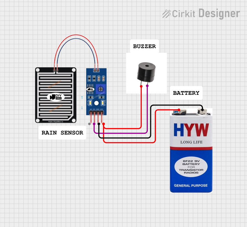 Open Project in Cirkit Designer
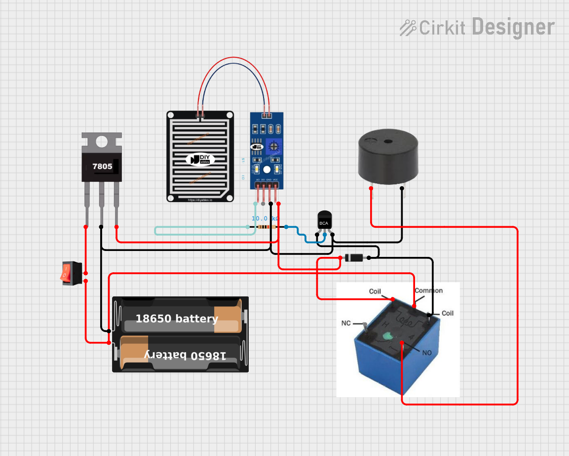 Open Project in Cirkit Designer
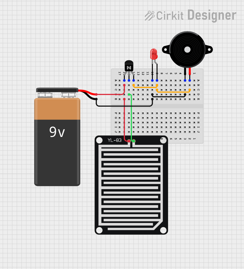 Open Project in Cirkit Designer
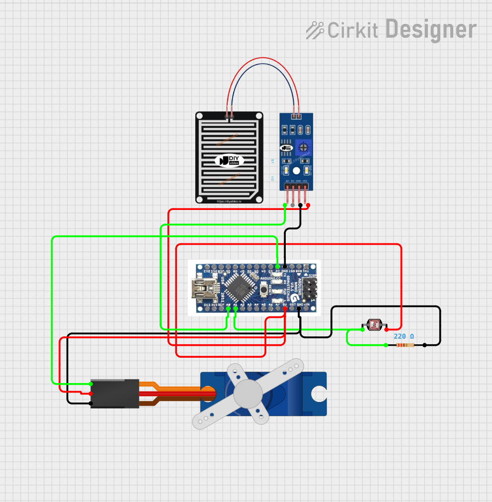 Open Project in Cirkit Designer
Explore Projects Built with RAIN SENSOR
Open Project in Cirkit DesignerOpen Project in Cirkit DesignerOpen Project in Cirkit DesignerOpen Project in Cirkit DesignerTechnical Specifications
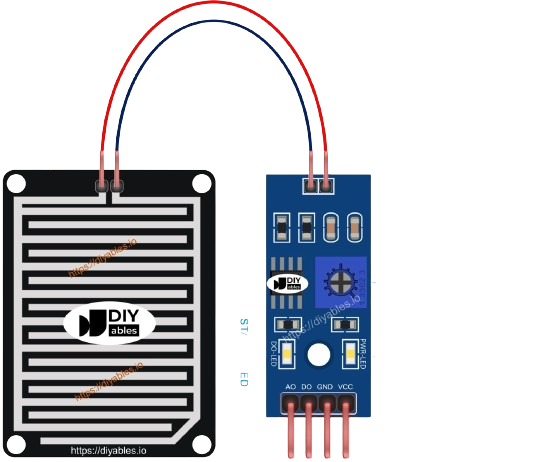
The rain sensor module generally consists of two parts: the rain detection board and the control board. Below are the key technical details:
- Operating Voltage: 3.3V to 5V
- Output Types: Digital (D0) and Analog (A0)
- Current Consumption: < 20mA
- Rain Detection Area: Typically 5cm x 4cm (varies by model)
- Output Signal:
- Digital: High (no rain) or Low (rain detected)
- Analog: Proportional to the amount of water on the detection board
- Adjustable Sensitivity: Via onboard potentiometer
- Dimensions: Varies by model, typically compact for easy integration
Pin Configuration and Descriptions
The rain sensor module typically has the following pins:
Control Board Pinout
| Pin Name | Description |
|---|---|
| VCC | Power supply input (3.3V to 5V) |
| GND | Ground connection |
| D0 | Digital output pin (High/Low signal based on rain detection) |
| A0 | Analog output pin (provides a voltage proportional to the water detected) |
Rain Detection Board
The rain detection board connects to the control board via two pins:
| Pin Name | Description |
|---|---|
| S | Signal pin (connects to the control board for rain detection) |
| GND | Ground connection |
Usage Instructions
How to Use the Rain Sensor in a Circuit
- Connect the Power Supply:
- Connect the
VCCpin to a 3.3V or 5V power source. - Connect the
GNDpin to the ground of your circuit.
- Connect the
- Connect the Output Pins:
- Use the
D0pin for digital output if you only need to detect the presence of rain. - Use the
A0pin for analog output if you need to measure the intensity of rain.
- Use the
- Adjust Sensitivity:
- Use the onboard potentiometer to adjust the sensitivity of the digital output. Turning it clockwise increases sensitivity, while turning it counterclockwise decreases it.
- Mount the Rain Detection Board:
- Place the rain detection board in an open area where it can be exposed to rain. Ensure it is mounted securely and avoid placing it in areas prone to splashing or submersion.
Example: Connecting to an Arduino UNO
Below is an example of how to connect and use the rain sensor with an Arduino UNO:
Circuit Connections
- Connect the
VCCpin of the rain sensor to the 5V pin on the Arduino. - Connect the
GNDpin of the rain sensor to the GND pin on the Arduino. - Connect the
D0pin of the rain sensor to digital pin 2 on the Arduino. - Optionally, connect the
A0pin of the rain sensor to analog pin A0 on the Arduino.
Arduino Code
// Define pin connections
const int digitalPin = 2; // Digital output pin from the rain sensor
const int analogPin = A0; // Analog output pin from the rain sensor

void setup() {
  pinMode(digitalPin, INPUT); // Set digital pin as input
  Serial.begin(9600);        // Initialize serial communication
}

void loop() {
  // Read digital output (rain detected or not)
  int rainDetected = digitalRead(digitalPin);

  // Read analog output (rain intensity)
  int rainIntensity = analogRead(analogPin);

  // Print the results to the Serial Monitor
  if (rainDetected == LOW) {
    Serial.println("Rain detected!");
  } else {
    Serial.println("No rain detected.");
  }

  Serial.print("Rain intensity (analog value): ");
  Serial.println(rainIntensity);

  delay(1000); // Wait for 1 second before the next reading
}
Important Considerations and Best Practices
- Placement: Ensure the rain detection board is placed in an open area where it can accurately detect rain. Avoid placing it under obstructions like roofs or trees.
- Waterproofing: While the detection board is designed to handle water, the control board should be protected from moisture to prevent damage.
- Cleaning: Periodically clean the detection board to remove dirt or debris that may affect its performance.
- Power Supply: Use a stable power supply to ensure accurate readings.
Troubleshooting and FAQs
Common Issues and Solutions
The sensor is not detecting rain:
- Check the connections to ensure they are secure.
- Verify that the power supply voltage is within the specified range (3.3V to 5V).
- Adjust the sensitivity using the onboard potentiometer.
False rain detection:
- Ensure the detection board is clean and free of debris.
- Check for condensation or splashes that may trigger false readings.
Analog readings are inconsistent:
- Verify that the detection board is properly connected to the control board.
- Ensure the control board is not exposed to moisture.
FAQs
Q: Can the rain sensor be used to measure rainfall intensity?
A: Yes, the analog output (A0) provides a voltage proportional to the amount of water on the detection board, which can be used to estimate rainfall intensity.
Q: Is the rain sensor waterproof?
A: The rain detection board is designed to handle water exposure, but the control board is not waterproof and should be protected from moisture.
Q: Can I use the rain sensor with a 3.3V microcontroller?
A: Yes, the rain sensor operates within a voltage range of 3.3V to 5V, making it compatible with 3.3V microcontrollers like the ESP32 or Raspberry Pi Pico.
Q: How do I clean the rain detection board?
A: Use a soft, damp cloth to gently wipe the detection board. Avoid using abrasive materials or submerging the board in water.