How to Use ESP32 Breakout Board für ESP32 / ESP32-S3 WROVER WROOM/DevKitC/NodeMCU Erweiterungsboard: Examples, Pinouts, and Specs
Introduction
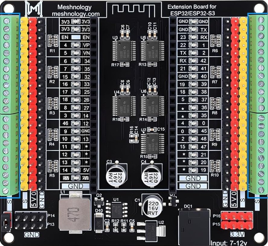
The ESP32 Breakout Board (Manufacturer: Meshnology, Part ID: L002030) is a versatile development platform designed to simplify prototyping and development with ESP32 and ESP32-S3 microcontrollers. This breakout board provides easy access to GPIO pins, power supply connections, and additional features, making it an ideal choice for IoT projects, embedded systems, and rapid prototyping.
Explore Projects Built with ESP32 Breakout Board für ESP32 / ESP32-S3 WROVER WROOM/DevKitC/NodeMCU Erweiterungsboard

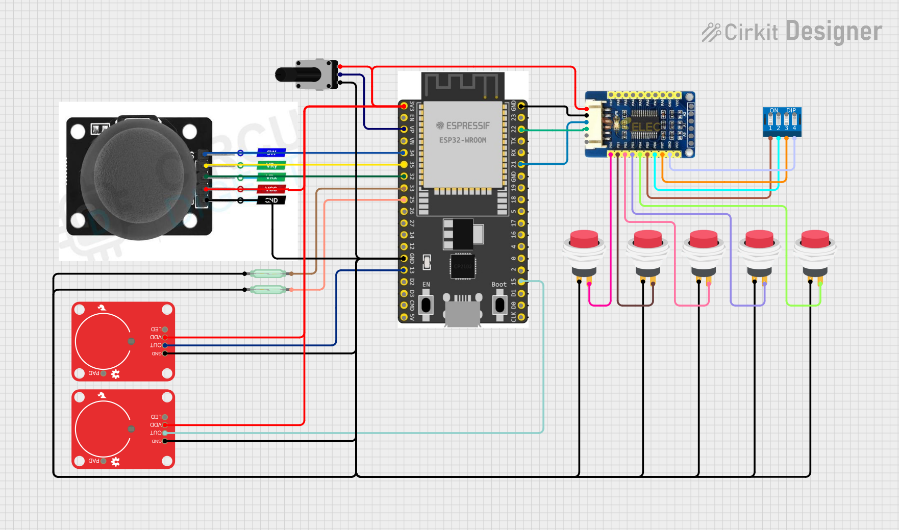

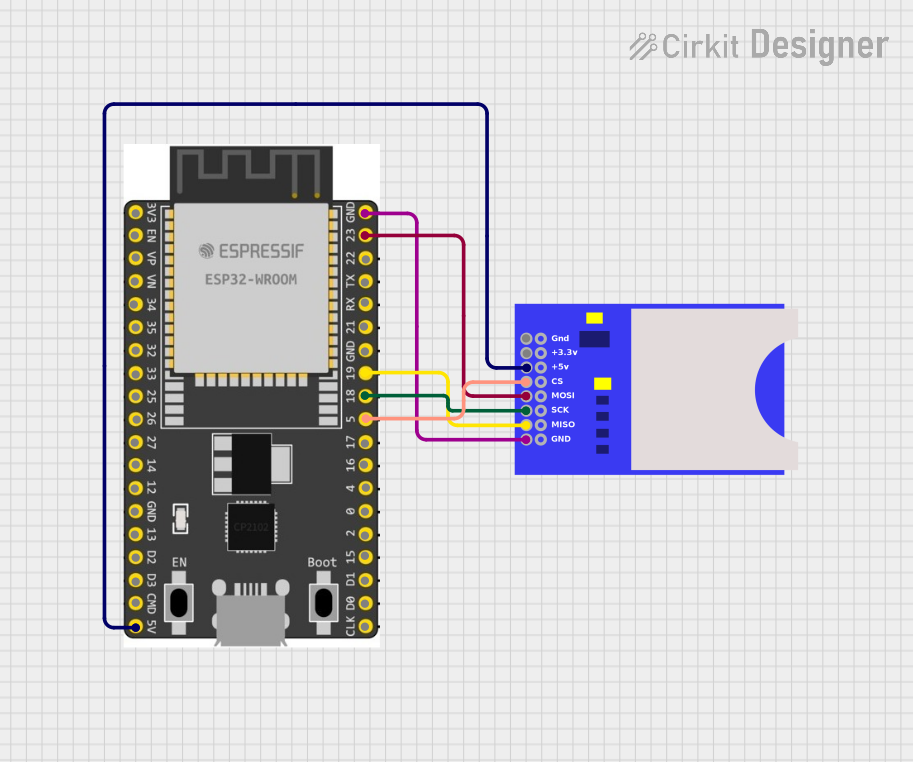
Explore Projects Built with ESP32 Breakout Board für ESP32 / ESP32-S3 WROVER WROOM/DevKitC/NodeMCU Erweiterungsboard
Common Applications and Use Cases
- IoT (Internet of Things) devices and smart home applications
- Prototyping and testing ESP32/ESP32-S3-based projects
- Educational purposes for learning microcontroller programming
- Wireless communication projects using Wi-Fi and Bluetooth
- Sensor integration and data acquisition systems
Technical Specifications
Key Technical Details
- Supported Microcontrollers: ESP32, ESP32-S3 (WROVER, WROOM, DevKitC, NodeMCU)
- Input Voltage: 5V (via USB) or 3.3V (via external power supply)
- GPIO Access: All ESP32/ESP32-S3 GPIO pins are broken out
- Communication Interfaces: UART, SPI, I2C, PWM, ADC, DAC
- USB Interface: Micro-USB for power and programming
- Onboard Features:
- Reset and Boot buttons
- Power LED indicator
- 3.3V and 5V power rails
- Dimensions: 60mm x 40mm x 10mm
- Operating Temperature: -40°C to 85°C
Pin Configuration and Descriptions
The breakout board provides access to all GPIO pins of the ESP32/ESP32-S3 microcontroller. Below is the pinout description:
| Pin Name | Description | Notes |
|---|---|---|
| VIN | Input voltage (5V) | Power input via USB or external source |
| GND | Ground | Common ground for the circuit |
| 3V3 | 3.3V power output | For powering external components |
| GPIO0 | General-purpose I/O pin 0 | Used for boot mode selection |
| GPIO1 | General-purpose I/O pin 1 | UART TX (default) |
| GPIO2 | General-purpose I/O pin 2 | Can be used for PWM or ADC |
| GPIO3 | General-purpose I/O pin 3 | UART RX (default) |
| GPIO4-39 | General-purpose I/O pins 4 to 39 | Configurable for various functions |
| EN | Enable pin | Active high to enable the ESP32 |
| RST | Reset pin | Resets the microcontroller |
Note: Some GPIO pins may have specific functions or limitations. Refer to the ESP32/ESP32-S3 datasheet for detailed pin capabilities.
Usage Instructions
How to Use the Component in a Circuit
Powering the Board:
- Connect the board to a 5V USB power source using the micro-USB port.
- Alternatively, supply 3.3V directly to the 3V3 pin.
Programming the ESP32/ESP32-S3:
- Connect the board to your computer via the micro-USB cable.
- Install the necessary USB-to-serial drivers (e.g., CP210x or CH340, depending on the ESP32 module).
- Use the Arduino IDE or ESP-IDF to upload your code.
Connecting Peripherals:
- Use the GPIO pins to connect sensors, actuators, or other peripherals.
- Ensure that the voltage levels of connected devices are compatible with the ESP32 (3.3V logic).
Boot and Reset:
- Press the Boot button while resetting the board to enter programming mode.
- Use the Reset button to restart the microcontroller.
Important Considerations and Best Practices
- Avoid exceeding the maximum current rating of the GPIO pins (12mA per pin).
- Use level shifters if interfacing with 5V logic devices.
- Ensure proper grounding to avoid noise or instability in the circuit.
- Use decoupling capacitors near power pins for stable operation.
- For Wi-Fi or Bluetooth applications, ensure the antenna area is not obstructed.
Example Code for Arduino UNO Integration
Below is an example of how to blink an LED connected to GPIO2 of the ESP32 breakout board:
// Example: Blink an LED connected to GPIO2 of the ESP32 breakout board

// Define the GPIO pin for the LED
#define LED_PIN 2

void setup() {
  // Initialize the LED pin as an output
  pinMode(LED_PIN, OUTPUT);
}

void loop() {
  // Turn the LED on
  digitalWrite(LED_PIN, HIGH);
  delay(1000); // Wait for 1 second

  // Turn the LED off
  digitalWrite(LED_PIN, LOW);
  delay(1000); // Wait for 1 second
}
Note: Ensure the LED is connected to GPIO2 with a current-limiting resistor (e.g., 220Ω) to prevent damage.
Troubleshooting and FAQs
Common Issues and Solutions
ESP32 Not Detected by Computer:
- Ensure the USB cable is functional and supports data transfer.
- Install the correct USB-to-serial driver for your operating system.
Unable to Upload Code:
- Check that the board is in programming mode (press and hold the Boot button while resetting).
- Verify the correct COM port and board settings in the Arduino IDE or ESP-IDF.
GPIO Pins Not Working as Expected:
- Confirm that the pins are not being used for other functions (e.g., UART, ADC).
- Check for short circuits or incorrect wiring.
Wi-Fi/Bluetooth Signal Issues:
- Ensure the antenna area is clear of obstructions.
- Avoid placing the board near metal objects or sources of interference.
FAQs
Can I power the board with a battery? Yes, you can use a 3.7V LiPo battery with a suitable voltage regulator to provide 3.3V to the 3V3 pin.
What is the maximum current output of the 3.3V pin? The 3.3V pin can supply up to 500mA, depending on the input power source.
Is the board compatible with ESP-IDF? Yes, the board is fully compatible with ESP-IDF for advanced development.
Can I use this board with other ESP32 modules? Yes, the board supports various ESP32 modules, including WROVER, WROOM, DevKitC, and NodeMCU.
For additional support, refer to the official ESP32 documentation or contact Meshnology customer support.