How to Use ZMCT103C: Examples, Pinouts, and Specs
Introduction
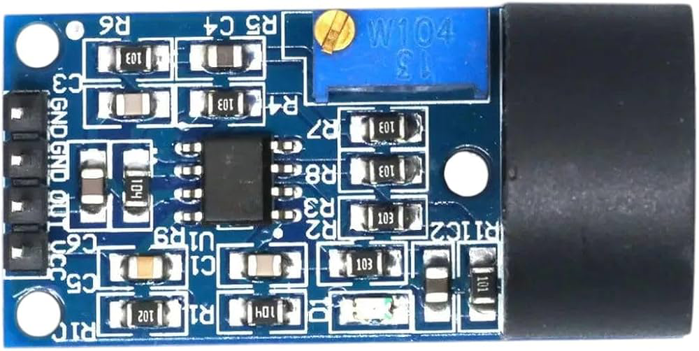
The ZMCT103C is a high-precision current sensor designed to measure both AC and DC currents using a Hall effect sensing element. It provides an isolated output voltage that is proportional to the current flowing through the conductor, ensuring safe and accurate current measurement. This component is widely used in power monitoring, energy management systems, and industrial control applications due to its reliability and precision.
Explore Projects Built with ZMCT103C


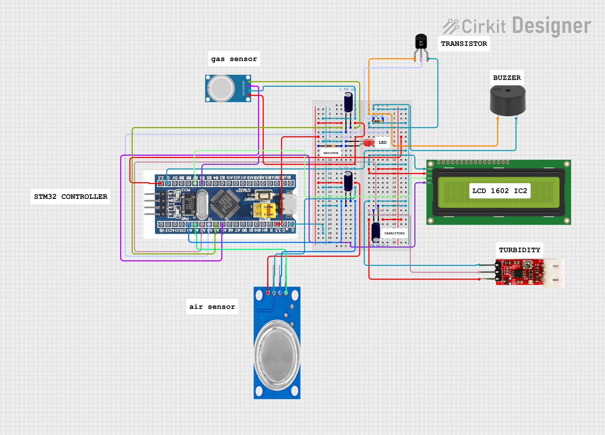
Explore Projects Built with ZMCT103C
Common Applications
- Power monitoring in residential, commercial, and industrial systems
- Energy metering and management
- Overcurrent protection in electrical circuits
- Motor control and load monitoring
- Renewable energy systems (e.g., solar inverters)
Technical Specifications
The ZMCT103C is designed to deliver high accuracy and isolation in current sensing applications. Below are its key technical details:
Key Parameters
| Parameter | Value |
|---|---|
| Measurement Range | 0–5A (typical) |
| Output Voltage Range | 0–5V (proportional to current) |
| Supply Voltage | 5V DC |
| Accuracy | ±0.5% |
| Isolation Voltage | 2.5 kV |
| Operating Temperature | -25°C to +85°C |
| Frequency Range | 50 Hz to 1 kHz (AC) |
Pin Configuration
The ZMCT103C has a simple pinout for easy integration into circuits. Below is the pin configuration:
| Pin Number | Pin Name | Description |
|---|---|---|
| 1 | VCC | Power supply input (5V DC) |
| 2 | GND | Ground connection |
| 3 | VOUT | Output voltage proportional to the measured current |
| 4 | NC | Not connected (leave unconnected) |
Usage Instructions
The ZMCT103C is straightforward to use in current sensing applications. Follow the steps below to integrate it into your circuit:
Circuit Connection
- Power Supply: Connect the
VCCpin to a stable 5V DC power source and theGNDpin to the ground of your circuit. - Current Measurement: Pass the conductor carrying the current to be measured through the sensor's aperture.
- Output Signal: Connect the
VOUTpin to an analog input of a microcontroller or an ADC (Analog-to-Digital Converter) to read the output voltage.
Important Considerations
- Ensure the current flowing through the conductor does not exceed the sensor's maximum range (5A) to avoid saturation or damage.
- Use proper decoupling capacitors (e.g., 0.1 µF) near the
VCCpin to minimize noise. - The sensor's output is proportional to the current; calibrate your system to interpret the voltage correctly.
- Avoid placing the sensor near strong magnetic fields, as they may interfere with the Hall effect sensing.
Example: Using ZMCT103C with Arduino UNO
Below is an example of how to use the ZMCT103C with an Arduino UNO to measure current:
// ZMCT103C Current Sensor Example with Arduino UNO
// Connect VCC to 5V, GND to GND, and VOUT to A0 (analog input)

const int sensorPin = A0;  // Analog pin connected to ZMCT103C VOUT
float sensitivity = 1.0;  // Sensitivity factor (adjust based on calibration)
float voltage = 0.0;      // Variable to store sensor output voltage
float current = 0.0;      // Variable to store calculated current

void setup() {
  Serial.begin(9600);  // Initialize serial communication
}

void loop() {
  // Read the analog value from the sensor
  int sensorValue = analogRead(sensorPin);

  // Convert the analog value to voltage (assuming 5V reference)
  voltage = (sensorValue / 1023.0) * 5.0;

  // Calculate the current based on the sensor's sensitivity
  current = voltage * sensitivity;

  // Print the current value to the Serial Monitor
  Serial.print("Current: ");
  Serial.print(current);
  Serial.println(" A");

  delay(1000);  // Wait for 1 second before the next reading
}
Calibration
- The
sensitivityvariable in the code should be adjusted based on the sensor's output characteristics and the specific application. - To calibrate, measure a known current and adjust the sensitivity factor until the output matches the expected value.
Troubleshooting and FAQs
Common Issues
No Output Voltage:
- Ensure the sensor is powered with a stable 5V DC supply.
- Verify that the conductor carrying the current is properly passed through the sensor's aperture.
Inaccurate Readings:
- Check for noise in the power supply and add decoupling capacitors if necessary.
- Ensure the sensor is not exposed to external magnetic fields.
Output Voltage Saturation:
- Confirm that the current does not exceed the sensor's maximum range (5A).
- If higher currents are expected, consider using a different sensor with a higher range.
FAQs
Q: Can the ZMCT103C measure DC currents?
A: Yes, the ZMCT103C can measure both AC and DC currents due to its Hall effect sensing element.
Q: How do I interpret the output voltage?
A: The output voltage is proportional to the current flowing through the conductor. Use the sensor's sensitivity factor to calculate the current from the voltage.
Q: Is the ZMCT103C suitable for high-frequency applications?
A: The ZMCT103C is optimized for frequencies between 50 Hz and 1 kHz. For higher frequencies, consider a sensor designed for such applications.
Q: Can I use the ZMCT103C with a 3.3V microcontroller?
A: While the sensor requires a 5V supply, its output can be interfaced with a 3.3V microcontroller using a voltage divider or level shifter.
By following this documentation, you can effectively integrate the ZMCT103C into your projects for accurate and reliable current measurement.